AKP 0.00% $6.20 audio pixels holdings limited

Ann: Quarterly Activities/Appendix 4C Cash Flow Report, page-200

  1. 1,180 Posts.
    lightbulb Created with Sketch. 697
    and another

    Figures
    • FT_1
    • FT_2
    • FT_3
    • FT_4
    • FT_5
    • FT_6
    • FT_7

    App Number:
    CN202311447094.2
    File Date:
    2023-11-02
    PubNum:
    CN117177150A
    Pub Date:
    2023-12-05
    Abstract
    The invention discloses a sound-generating unit, a preparation method thereof, and a digital speaker. It relates to the technical field of digital speakers and provides a technical solution that can solve the problem that the existing fixed-thickness diaphragm may not meet the device's requirements for the sound-generating unit. The sound-generating unit includes: an upper substrate structure and a lower substrate structure bonded together, a support structure provided on the upper substrate structure, and a diaphragm structure. The lower substrate structure has a sound-generating cavity arranged toward the upper substrate structure. The sound-generating unit has a plurality of sound-generating channels that penetrate the upper substrate structure and the support structure. The plurality of sound-generating channels are arranged opposite to the sound-generating cavity. The two ends of the diaphragm structure are provided with On the support structure, the middle area is suspended above the support structure, and the middle area of the diaphragm structure includes the center of the diaphragm and the diaphragm cantilever beams located on both sides of the diaphragm center. The center of the diaphragm is suspended in multiple sound channels. above, the thickness of the diaphragm center is smaller than the thickness of the diaphragm cantilever beam.
    Claims Translate
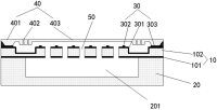
    1. A sound-generating unit, characterized in that it is used in a digital speaker, and the sound-generating unit includes: an upper substrate structure and a lower substrate structure bonded together, a support structure provided on the upper substrate structure, and a diaphragm structure located on the support structure;
    Wherein, the lower substrate structure has a sound-generating cavity disposed toward the upper substrate structure, and the sound-generating unit has a plurality of sound-generating channels penetrating the upper substrate structure and the support structure, and the plurality of sound-generating channels are connected with the The sound-emitting cavities are arranged oppositely, both ends of the diaphragm structure are arranged on the support structure, and a middle area is suspended above the support structure. The middle area of the diaphragm structure includes the center of the diaphragm and the center of the diaphragm. There are diaphragm cantilever beams on both sides of the diaphragm center. The diaphragm center is suspended above the plurality of sound-generating channels. The thickness of the diaphragm center is smaller than the thickness of the diaphragm cantilever beam.
    2. The sound-generating unit according to claim 1, wherein the upper substrate structure includes an upper substrate layer and an insulating layer disposed on a side of the upper substrate layer facing the lower substrate structure, wherein the plurality of A sound emitting channel penetrates the upper substrate layer and the insulating layer, and the volume resistivity of the upper substrate layer is less than 0.1Ω·cm.
    3. The sound-generating unit according to claim 2, wherein the support structure includes a support layer provided on the substrate layer and a plurality of support pillars provided on the support layer, and the plurality of sound-generating columns The channel runs through the support layer, and one support column is provided on the support layer between each adjacent two sound-generating channels. The support column is used to support the vibration when the center of the diaphragm vibrates. The center of the diaphragm is supported and limited.
    4. The sound-generating unit according to claim 1, wherein the diaphragm structure further includes support ends located at both ends of the diaphragm structure, and the diaphragm cantilever beam is connected between the support end and the vibrator. Between the film centers, the support end is provided on the support structure;
    The upper substrate structure also includes a first annular groove located on the periphery of the plurality of sound-generating channels, and the diaphragm cantilever beam is suspended above the first annular groove.
    5. The sound-generating unit according to any one of claims 1-4, characterized in that the diameter of each sound-generating channel includes 1um-10um.
    6. A digital speaker, characterized in that it includes a plurality of sound-generating units according to any one of claims 1 to 5, and the plurality of sound-generating units are arranged in an array.
    7. A method for preparing a sound-generating unit, characterized in that the method includes the following steps:
    An upper substrate structure and a lower substrate structure bonded together are provided; wherein the lower substrate has a sound-generating cavity;
    A support structure and a plurality of sound-generating channels are formed on the upper substrate structure; wherein the plurality of sound-generating channels are arranged opposite to the sound-generating cavity;
    A diaphragm structure is formed above the support structure, wherein both ends of the diaphragm structure are arranged on the support structure, and a middle area is suspended above the support structure. The middle area of the diaphragm structure It includes a diaphragm center and diaphragm cantilever beams located on both sides of the diaphragm center. The diaphragm center is suspended above the plurality of sound-generating channels. The thickness of the diaphragm center is smaller than the diaphragm cantilever beam. thickness of.
    8. The method of preparing a sound-generating unit according to claim 7, wherein forming a support structure and a plurality of sound-generating channels on the upper substrate structure includes:
    A front support structure is formed on the upper substrate structure, wherein the front support structure includes a front annular base disposed in an edge area of the upper substrate structure, and a plurality of arrays arranged in an array located in the middle area of the upper substrate structure. front support column;
    Performing a first patterning process on the upper substrate structure to form a first annular groove between the annular base and the plurality of front support columns;
    Deposit a second insulating layer on the front support structure and the first annular groove, and perform a second patterning process on the second insulating layer and the upper substrate structure to form a through-hole second insulating layer. layer and multiple sound-generating channels of the upper substrate structure to obtain a support structure, wherein the support structure includes an annular base arranged in the edge area of the upper substrate structure, and an array arranged in the middle area of the upper substrate A plurality of support columns, the plurality of sound-generating channels are arranged in an array, and each of the sound-generating channels is located between adjacent support columns.
    9. The method of manufacturing a sound-generating unit according to claim 8, wherein forming a diaphragm structure above the support structure includes:
    forming a sacrificial layer on the upper substrate structure and the support structure;
    A second annular groove is formed in the sacrificial layer, wherein the second annular groove is formed above the first annular groove, and the diameter and depth of the second annular groove are smaller than the first annular groove;
    A third annular groove is formed on the outer periphery of the second annular groove in the sacrificial layer, and the third annular groove penetrates the sacrificial layer;
    Deposit a polysilicon layer on the sacrificial layer, and perform a third patterning process on the polysilicon layer to form the diaphragm cantilever beam, wherein the diaphragm cantilever beam is located directly above the first annular groove ;
    The sacrificial layer is removed to obtain the diaphragm structure.
    Description Translate
    Technical field
    The present invention relates to the technical field of digital speakers, and in particular to a sound-generating unit and a preparation method thereof, as well as a digital speaker.
    Background technique
    Digital loudspeaker is a new sound-generating device based on Digital Sound Reconstruction (DSR) technology. Its principle is to form sound waves through a combination of pulses generated by high-frequency vibration of sound-generating units arranged in an array. Therefore, digital speakers have extremely high requirements on the vibration characteristics of the sound-emitting unit microfilm, especially high-frequency vibration parameters. Microfilms need to have extremely high resonant frequencies while being relatively small and easy to control. Existing fixed-thickness diaphragms may not meet the device's requirements for sound-generating units.
 
watchlist Created with Sketch. Add AKP (ASX) to my watchlist
arrow-down-2 Created with Sketch. arrow-down-2 Created with Sketch.