2 docs uploaded overnight - a cover letter from WWC (on behalf of Strata) re the the 3rd round RAIs and the WDEQ's comments on the acceptability of Strata's responses.
Cheers all, Krypt
PS Thanks hath88 on the other thread.
PPS Sorry to see you go moneymoneymoney and thanks for your contributions. -----------------------------------------------------------
Mr. Miles Bennett Land Quality Division, District 3 Wyoming Department of Environmental Quality 2100 West 5th Street Sheridan, WY 82801
RE: Submittal of 3rd Round Responses to Technical Comments on Strata Energy’s, Ross ISR Project Permit to Mine Application, TFN 5 5/217
Dear Mr. Bennett:
On behalf of Strata Energy, please find the enclosed materials. The materials have been prepared in response to WDEQ review comments to the Ross ISR Project Permit to Mine application. The package includes the following:
1) Responses to technical comments in a question and answer format, 2) Change index detailing the volume number, pages to be removed and replaced along with a brief description of the change (3rd round materials are shown in green) 3) Signed Form 8 for Michael E. Easley, and 4) Replacement page.
During the meeting between WDEQ and WWC on October 5, 2011, Glenn Mooney indicated that the financial assurance amount of $9.6 million appeared to be adequate for the proposed facility. Under this pretense, Strata has begun the work necessary to obtain a bond for the project. Strata continues to work with the Berger’s to obtain the Form 8.
Feel free to contact myself or Mr. Simpson at any time if you have questions or concerns regarding the enclosed response package.
Sincerely,
Benjamin Schiffer, P.G. Project Manager /bjs Encl: as noted CC: Mr. Tony Simpson (without enclosures) Mr. John Saxton, NRC (without enclosures) Mr. James Bashor, BLM-NFO (without enclosures) K:\Peninsula_Minerals\09142\Correspondence\DEQ Submittal\District 3 Cvr Ltr_Responses_DRAFT.docx ------------------------------------------------------------------------------------------------------------------------- 1 Response to 3rd Round Technical Comments, Ross ISR Project TFN 5 5/217 Deanna Hill Technical Review Comments Form 1 UIC 1. Please submit ensuring the bottom of each page is initialed and dated. Response: The original signed, initialed and dated form is enclosed/attached for Deanna Hill, LQD/DEQ; Cheyenne office. No changes were necessary to the copies in the permit. 2nd Round 1. Page A-4, item 6, Approved Acreage to Affect needs to be inserted. Response: An email was sent to Ms. Deanna Hill requesting that she insert the affected acreage onto Form 1. 3rd Round Response acceptable Form 3 1. Please submit ensuring the bottom of each page is initialed and dated. Response: The original signed, initialed and dated form is enclosed/attached for Deanna Hill LQD/DEQ; Cheyenne office. No changes were necessary to the copies in the permit. 2nd Round 1. Page A-8, notary neglected to insert the name of the individual she is acknowledging. Response: An email was sent to Ms. Deanna Hill requesting that Anthony J. Simpson be placed onto Form 3. 2 3rd Round Response acceptable Fees Acceptable. Appendix A Acceptable. Appendix B Acceptable. Appendix C 1. Please provide an originally signed appendix. Response: The original signed form is enclosed/attached for Deanna Hill, LQD/DEQ; Cheyenne office. No changes were necessary to the copies in the permit. 2nd Round Response acceptable 2. Please advise the page number or provide the tabulation of lands where there is no right to mine claimed with acreage (Chapter II, 2.(b)(iv)(G)(I) Response: Page C1 as submitted, states: Applicants legal right to mine covers all lands listed within the permit area. Therefore, a listing of lands where “no right to mine” is claimed (C-2) is not applicable. No changes were necessary to the copies in the permit. 2nd Round Response acceptable Surface Landowner Consent 1. Originally signed Surface Landowner’s Consent Forms 8 must be submitted to the Cheyenne office. 3 Response: Original signed Consent Form 8(s), less Berger are enclosed/attached for Deanna Hill of the Cheyenne office. No changes were necessary to the copies in the permit. 2nd Round Response acceptable 3rd Round 1. The Cheyenne office has not received originally signed consents for Harry J. Berger or Michael E. Easley. Response: The originally signed consent for Michael E. Easley has been submitted. Strata continues to work with the Berger’s to obtain the Form 8. Reclamation Performance Bond – not a completeness issue 1. An acceptable bonding instrument must be in place before approval may be granted. Response: An acceptable bonding instrument will be provided as a condition of final permit approval. 2nd Round Response acceptable Miscellaneous – not a completeness issue 1. Please provide labeled dividers to separate the various sections of the application. Response: Section dividers are provided for the Adjudication Volume. The change index indicates the location for the tabs. 2nd Round Response acceptable 4 Glenn Mooney Technical Review Comments Adjudication 1. Appendix A – Surface Owners This review found some serious structural problems with Appendix A The major problem is with duplication. The listing of lands in Appendix A runs from Page A-16 to A-78c and then the listing is repeated in Pages A-79 through A-142. Following is a summary of the makeup of Appendix A: Pages A-16 to A-78c Pages A-79 to A-142 Tract and Section Page No. Page No.__________ SESE-12 A-20/A36 A-119 SWSW-12 A-36 A-119 NENE-13 A-20/A-20 A-121 NWNE-13 A-22 A-121 SWNE-13 A-22 A-121 SENE-13 A-22 A-121 NESE-13 A-22 A-121 NWSE-13 A-22 A-121 SWSE-13 A-25 A-123 SESE-13 A-25 A-127 NWNE-24 A-24 A-129 NENE-24 A-23 A-131 SWSW-7 A-38 A-79 SESW-7 A-39 A-81 SWSE-7 A-38 A-79 SESE-7 A-38 A-79 NWNW-18 A-50 A-86 5 Pages A-16 to A-78c Pages A-79 to A-142 Tract and Section Page No. Page No.__________ NENW-18 A-50 A-86 NWNE-18 A-27 A-84 NENE-18 A-28 A-99 SWNW-18 A-50 A-86 SENW-18 Not found A-86 SWNE-18 A-27 A-96 SENE-18 A-27 A-96 W/2SENW-17 A-37 A-141 NWSW-18 Not found A-86 NESW-18 Not found A-86 NESE-18 A-27 A-96 NWSE-18 A-76 (Claim only) A-96, A-133 SWSW-18 Not found A-86 SESW-18 Not found A-86 SWSE-18 A-42 A-89 W/2SESE-18 A-42 A-92 NWNE-24 A-24 A-129 NENE-24 A-23 A-131 NWNW-19 A-16 A-111 NENW-19 A-16 A-111 NWNE-19 A-45 A-103 W/2NENE-19 A-42 A-107 E/2SWNW-19 A-16 A-111 SENW-19 A-16 A-111 SWNE-19 A-42 A-104 SENE-19 A-42 A-104 E port. NWSW-19 A-16 A-111 NESW-19 A-16 A-111 NWSE-19 A-42 A-104 NESE-19 A-42 A-104 Please correct and eliminate the above-listed duplications. Response: A 9:00 am, May 13, 2011 meeting at the District 3 LQD/DEQ office with Glenn Mooney and Niles Veal, concluded that Adjudication pages A-16 thru A-142 are acceptable as originally submitted. No further response is required. 2nd Round Response acceptable 2. Appendix B, Adjacent Surface Owners No problems were found with this section. No response is required. 6 Response: No response required. 3. Appendix C, Legal Land Description No problems were found with this section. No response is required. Response: No response required. 4. Surface Owner Consent Surface Owner Consent is required for the Harry J. Berger Trust lands in Sections 17 and 19. Response: Required Surface Owner Consent for Harry J. Berger trust lands will be provided during the final round of technical comments. 2nd Round 4. Strata replied to my request for Surface Owner Consent from the Harry J. Berger Trust lands in Sections 17 and 19 with a statement that the consent will be supplied during the final round of technical comments. Response: Strata Energy is working toward resolving this issue. 3rd Round Response acceptable 5. Appendix E Many of the features required on the Appendix E maps are shown instead on adjudication Maps Exhibit 1, Surface Ownership, Structures, and Grazing Leases and Exhibit 4, Rights of Ways and Easements. This is acceptable; no response is required. Response: No response required. Mine Plan 6. Section 4.1, Well Field Data Package, Page 4-1 7 a. It is not clear what items will be submitted in the well field data packages. Please provide a bulleted list of the package contents. b. The discussion in Section 4.1.5, Constructions Considerations and Topsoil Handling should be limited to stating that the locations of topsoil stockpile for each well field will be depicted on the map in the well field data package for that well field. There should be a cross-reference to the main section on topsoil handling in Section 2.4 on Page 2-3. Response: a. Section 4.1 was modified to include a bulleted list of the well field package contents. 2nd Round a. A bulleted list of the package contents was provided as requested. Does the last item, “Abandonment Records” refer to abandonment of wells or a search for and handling of abandoned exploration drill holes that may be located within the well field? The latter is preferred. Please explain. Response: The “Abandonment Records” does refer to abandoned exploration drill holes. The text has been revised to clearly indicate that it includes exploration drill holes. 3rd Round Response acceptable b. The text in Section 4.1.4 (please note that the response to comment 7 eliminated the original Section 4.1.4; Section 4.1.5 is now Section 4.1.4) has been revised as suggested and now includes a cross reference to Section 2.4. Reference Exhibits MP.2-1 and MP.2-2 for topsoil stockpile locations. 2nd Round Response acceptable 7. Section 4.3, Conceptual Wellfield Package, Page 4-14 Please explain how the “Conceptual Wellfield Data Package in this section is different from the Wellfield Data Page described in Section 4.1 discussed above? Please consolidate these sections into one concise section. Response: The text was revised to clarify the differences between the two sections as well as to minimize redundancy. Sections 4.1 and 4.3 were revised. Section 4.1 now presents the contents of the well field package and includes an introductory section that further clarifies the contents of the well field package. Section 4.3 discusses the procedures for 8 developing the well field package. To minimize redundancy Section 4.1.4 was combined with Section 4.3.1, which resulted in Section 4.1.5 being renumbered to Section 4.1.4. 2nd Round Response acceptable 8. Section 5.8, Water Balance, Page 5-8 The water balance calculations must show the system is capable of handling an excursion while both restoration and mining operations are occurring in other well fields. Likelihood of an excursion seems high because of the nearness of well fields. Response: A new paragraph was added to the end of section 5.8 to further describe the available liquid waste capacity in the event of an excursion. As is discussed in the new paragraph, excess capacity will be maintained within the lined retention ponds that would be available in the event of an excursion. Furthermore, excess capacity is also available within the deep disposal wells. In the event that more capacity is needed to control an excursion, Strata will make operational changes as necessary to manage the additional waste streams resulting from the excursion. 2nd Round Response acceptable 9. Section 5.9.1, Upper Control Limits and Excursion Monitoring, Page 5-13 Strata proposes to use sulfate as a substitute for chloride as an excursion parameter in the deep monitor wells because of the high chloride values now found there. Sulfate as an excursion parameter was tried as an excursion parameter before, admittedly in the Wasatch Formation, but its high natural variability caused false excursion problems. False excursions would be also more likely because Strata proposes to call an excursion if only one parameter increases more than 20%. Strata should be certain the variability of sulfate levels in the deep aquifer and the proposed 20% increase will not result in false excursions. Response: Strata agrees with the reviewer that there is variability in sulfate concentrations within individual wells in the DM aquifer. Strata is continuing to conduct quarterly water quality monitoring of DM wells, which will determine if the variability in sulfate concentrations noted between the first four quarterly samples will continue over time, or if variability decreases over time. Ultimately, the reliability of sulfate as an excursion parameter will be addressed in the baseline well field package assembled for the first mining unit, which will include a statistical analysis of sulfate variability along with proposed UCL concentrations. 9 The major ion chemistry of groundwater from the DM unit is very distinct from that of the OZ unit. The 2010 quarterly water quality sampling of the six DM monitoring wells indicates consistent water quality, both spatially and temporally. The most distinctive water quality characteristic of the DM unit relative to the other monitored aquifers in the area is relatively high concentrations of chloride, which is the dominant anion. As discussed in Section 5.9.1, sulfate concentrations in the DM unit are consistently low however, being typically less than 150 mg/L. However, the ambient levels of sulfate in the OZ unit range between 300 to more than 900 mg/L and are expected to increase by at least 150 mg/L during mining operations. Strata commits to the use of sulfate along with conductivity and alkalinity as an excursion parameter in the DM unit. As such, the fourth sentence of the first full paragraph on page 5-13 was revised to make this commitment. 2nd Round Response acceptable 10. Section 7.2.2.1.3, Land Application, Page 7-13 Strata states that radium is likely to pass through the reverse osmosis (r/o) units in undesirable amounts. Selenium is also known to pass through r/o units. Is there likely to be significant quantities of selenium in the waste water to be treated and if so, how will it be handled? Response: Strata does not anticipate that selenium concentrations in the permeate will be present in concentrations above 0.1 mg/L (See Table MP.7-1) Further, selenium does not become an issue unless water containing selenium is proposed for land application or surficial discharge. In order for land application to occur, a permit revision will be required. The topic of permeate selenium concentrations would be addressed in detail in the revision that would be required to accommodate land application as a water management alternative. No changes were made to the permit in response to this comment. 2nd Round Response acceptable 11. Section 7.2.2.1.3, Land Application, Page 7-13 Because of the potential for contamination by radium, any system that uses land application or SDI should be designed as fail-safe so that a wrong valve setting, blocked filter or similar situation cannot result in untreated water allowed to flow to the disposal site. The clean-up of lands contaminated by radium is likely to be extremely expensive. Response: In order for land application or SDI to occur, a permit revision will be required. The topic of radium removal prior to land application would be addressed in detail in the revision 10 that would be required to accommodate land application as a water management alternative. No changes were made to the permit in response to this comment. 2nd Round Response acceptable 12. Section 9.5.2.4.3, Potential Reclamation Impacts to the SM, OZ and DM Aquifers., Page 9-45 Please remove the reference to Non Coal Rules and Regulations, Chapter 8. Chapter 8 covers the abandonment of exploration drill holes under Drilling Notifications only. Refer to Section 8 of Chapter 11 for the regulations relating to wells using during in situ mining. Response: The text in Section 9.5.2.4.3 has been updated as suggested. 2nd Round Response acceptable 13. Section 9.5.2.4.3, Potential Reclamation Impacts to the SM, OZ and DM Aquifers, Page 9-45 The last sentence of this section states “A well abandonment and plugging methodology will be provided in the Class III Injection Permit Application.” This mining permit application is the Class III Injection Permit Application under Wyoming law. Please provide well abandonment and plugging information in this document. Response: The well abandonment plan is included as Addendum RP-1. The text in Section 9.5.2.4.3 has been updated to reference this addendum. 2nd Round 13. Section 9.5.2.4.3, Potential Reclamation Impacts to the SM, OZ and DM Aquifers, Page 9-45. Strata replied that the well abandonment plan was provided as Addendum RP-1. Page RP-1-2 was found at the end of the pages intended for insertion into the Reclamation Plan, but this page only addresses borehole abandonment and says nothing about well abandonment. Please include information on well abandonment techniques. Response: The text has been revised to include well abandonment. 11 3rd Round Response acceptable 14. Section 11.0, Reporting Procedures, Page 11-1 This section only refers to the information presented in the Annual Report. Please add the information and procedures to be presented in the Quarterly Reports, Excursion Reports, Spill Reports and other required reports. Response: Table 11-1 includes the items that will be presented on the quarterly reports and on the special reports, such as excursion reports, submitted on an as needed bases. A special section was devoted to describing the annual report because many of the items presented in the annual report are not included on Table 11.1. The first and second paragraphs within Section 11.0 were rewritten to further clarify what will be contained within the quarterly reports and special reports. 2nd Round Response acceptable 15. Duplication The duplication of several sections is confusing. For instance, Deep Disposal Wells are discussed in Section 2 on Page 2-7, in Section 7 on Page 7-15 and in Section 9 on Page 9-63. Lined Detention Ponds are discussed in Section 2.8 on Page 2-8, in Section 7 on Page 7-24 and also in Section 9 on Page 9-63. Excursions are discussed in Section 5 on Page 5-12 and in Section 9 on Page 9-60. This duplication is confusing and misleading because the subject is not discussed in the same detail in every section, leading one to the belief that the subject is not adequately addressed if only one section is found. It will also cause problems in updating the permit document. Please address each subject in adequate detail in one section and cross-reference that section to the other sections. Response: Revised text in Sections 2.7, 2.8, and 5.9.2 were revised to clarify where formal commitments for deep disposal wells, lined ponds and excursions are located. 2nd Round 15. Duplication. Some cross-referencing was done as requested, but there were no discernible changes to the descriptions of excursion monitoring as described in Section 5.9.1 on Page 5-12 and Section 9.5.4.2.1 on Page 9-60. Please explain. 12 Response: Text has been added to Section 9.5.4.2.1 to reference and clarify the descriptions of excursion monitoring. 3rd Round Response acceptable 16. Exhibit MP.2.6, Continuous Barrier Wall This exhibit depicts a fence around the plant and ponds area, but not as separate fence for the ponds. It is necessary for the ponds to be fenced separately in order to bar access to big game animals and loose livestock from the ponds area. These animals could be trapped in the ponds and would severely damage the pond liners. Response: The entire CPP perimeter will be enclosed by a livestock and big game-proof fence. Access into the facility will be through gates (tipping type, also livestock and big game proof) that will be closed at all times except when a vehicle is entering the site. The site perimeter will be secure to big game and livestock, eliminating the need for additional fencing around the ponds. No changes were made to the permit in response to this comment. 2nd Round Response acceptable 17. Exhibit MP.2.6, Continuous Barrier Wall This exhibit depicts one of the deep disposal wells being located at the back corner of the pond enclosures. Strata should ensure that large equipment such as drilling rigs and work-over rigs will be able to negotiate the tight access route to this well or provide an alternate access route. Response: The disposal well depicted on this Exhibit would be drilled prior to construction of the other facilities, eliminating the need for drill rig access. Workover rigs are truck mounted, and will be able to access the disposal well using the proposed access road without modification. No changes were made to the permit in response to this comment. 2nd Round Response acceptable 13 18. Exhibit MP.2.6, Continuous Barrier Wall This exhibit states that the containment well will be installed into bedrock. However, this exhibit describes the underlying Lance Formation bedrock as consisting of very fine sandstone, siltstone and claystone which are saturated. This type of rock could transmit large quantities of groundwater. Please show evidence that a facility constructed to handle waste water will not in itself generate large amounts of water requiring handling and disposal. Response: Please see response to Larry Barbula Comment 5. Due to the low permeabilities of the underlying material, very little inflow is anticipated after the initial dewatering efforts. No changes were made to the permit in response to this comment. 2nd Round Response acceptable 19. Exhibit MP.2-7, Facilities Sediment Control Reservoir Since this reservoir is to be fitted with a geosynthetic liner, it should be fenced to prevent big game animals and loose livestock from becoming entrapped in it and also damaging the liner. Fencing of the plant area compound that also encloses the ponds is not enough because unless the gate is kept closed at all times except when a vehicle is passing through, animals will enter the compound. Response: As discussed in the previously, to ensure security of the facility, access will be controlled through tipping gates that will be closed at all times other than when a vehicle is entering the site, eliminating the need for fencing inside the perimeter. No changes were made to the permit in response to this comment. 2nd Round Response acceptable 20. Exhibit MP.4-2, Proposed Drill Hole Installation Methods This map is mislabeled as it actually depicts well installation methods. Please relabel as “Proposed Well Installation Methods.” Response: Exhibit MP.4-2 was relabeled as “Proposed Well Installation Methods.” 14 2nd Round Response acceptable Reclamation Plan 21. Section 3.2.2, Estimated Topsoil Volumes and Replacement Depths, Page 3.3 This section should contain a commitment to rip the substrate for compaction reduction prior to topsoil replacement. This is especially true for areas such as roads and parking lots. Response: Preparation of the surface prior to topsoil placement is discussed in Section 3.2.1, which indicates that the surface will be ripped as needed to a depth of at least 2 feet. No changes were made to the permit in response to this comment. 2nd Round Response acceptable 22. Section 5.2, Description of Work, Page RP-3-9 The proposed groundwater restoration plan does not call for the use of any kind of reductant. While the use of a reductant may not be necessary, its use is considered BPT and it should be listed as a potential restoration technique. Response: Strata will evaluate the use of chemical reductants during groundwater restoration. However, at this time, safety implications and feed mechanisms have not been addressed sufficiently to allow for proper analysis. Following the necessary analysis and if determined to be effective and safe, Strata would prefer to pursue this restoration alternative as a revision to the Ross ISR Project Permit to Mine at a later date. No changes were made to the permit in response to this comment. 2nd Round Response acceptable 23. Section 5.7, Containment Wall, Page RP3-3 The last sentence of the first paragraph of this section states “The remaining trench will be backfilled with topsoil and seeded.” This is not acceptable. The use of topsoil for backfilling trenches is not acceptable. Please change to “The remaining trench will be backfilled with subsoil, retopsoiled and seeded.” 15 Response: The text in Section 5.7 of Addendum RP-3 has been updated as requested. 2nd Round 23. Section 5.7, Containment Wall, Page RP3-3. The requested change to the reclamation plan text was made as requested. However, the original page was double-sided and the replacement page was single-sided. Replacement of the page will create a discontinuity. This is also true of replacement Page RP-1-2. Please provide replacement pages that are double-sided. Response: The second page of the double sided text was inadvertently left out. The updated double-sided pages have been submitted. 3rd Round Response acceptable 24. Section 6.0, Reclamation Cost Estimates, Page 6-1 A detailed review of the reclamation costs will follow once certain costs have been worked out within Land Quality internally and it is certain no major changes will be made to mine and reclamation plans. Response: No response necessary. 2nd Round 24. Section 6.0, Reclamation Cost Estimates, Page 6-1. I will continue to hold off on a detailed review of the reclamation costs until it is certain no major changes will be made to mine and reclamation plans. Response: No response necessary. 3rd Round 24. Section 6.0, Reclamation Cost Estimates, Page 6-1 I will continue to hold off on a detailed review of the reclamation costs until it is certain no major changes will be made to mine and reclamation plans. Response: During the meeting between WDEQ and WWC on October 5, 2011, it was stated by Glenn Mooney that the bond amount of $9.6 million appeared to be adequate for the proposed facility. 16 Mark Taylor Technical Review Comments Appendix D-5, Geology 1. Addendum D5-2, Drillhole Tabulations: This addendum contains a list of abandoned drill holes as required by LQD R&R Chapter 11, Sec. 3(a)(xii), however, the map of these holes is provided in the Reclamation Plan. Please revise this addendum to provide a cross-reference to Reclamation Plan Exhibit RP-1-1. (MT) Response: A reference to Exhibit RP-1-1 has been added to the Appendix D-5 narrative (page D5-10) and to Addendum D5-2, Table 1. 2nd Round Response acceptable Appendix D-6, Hydrology 2. Section D6.2.2.2, Monitoring/Testing Program, pg. D6-16, last paragraph: This text, as well as text at several other locations in this permit application state “…centralizers were placed at 60-foot intervals.” However, LQD R&R Chapter 11, Section 6(e) requires “centralizers placed at a maximum spacing of one per forty feet.” Please explain this apparent deficiency. (MT) Response: The six existing baseline monitoring well clusters consist of 27 wells, and each well was constructed with 5-inch (O.D. of 5.56 inches) CertainTeed Certa-LokTM SDR 17 (rated 250 psi) PVC well casing that extends from ground level to the top of the target aquifer interval. Borehole diameters are 8.75 inches and the integral bell (female) end of each 20-foot long casing section has an O.D. of 6.25 inches. Manufactured PVC centralizers having an I.D. of 5.82 inches and an O.D. of approximately 8.63 inches are slid over the male end of every third joint of casing as the casing string is assembled and lowered into the borehole. The centralizers are designed to slide freely on the casing and thus “float” as necessary between the adjacent bell ends. Only the deepest centralizer, which is set just above the top of the target aquifer, is solidly affixed to the casing with stainless steel screws that do not penetrate the inner wall of the casing. As the casing string is lowered through the final 20 feet, the centralizers tend to stay in the most constricted segments of the borehole, effectively centering the casing in the tightest intervals and ensuring optimum annular space for a continuous, 360-degree seal between the casing and borehole. Placement of each well’s annular seal was witnessed by an experienced, professional geologist (registered in Wyoming). The spacing for the casing centralizers is described in Section D6.2.2.2 as 60 feet; however, depending on the position of the most constricted segments of the borehole, the centralizer spacing could be as little as approximately 40 feet and as much as 17 approximately 80 feet, with the average spacing at approximately 60 feet. To comply with the LQD R&R Chapter 11, Section 6(e) requirement, Strata has committed to placing a PVC centralizer “on the casing string at a maximum spacing of one per 40 feet,” for all new monitor, recovery, and injection wells (see Section 4.2.1 in the Mine Plan). By placing a sliding-type PVC centralizer on every other 20-foot long joint of casing rather than on every third joint, the centralizer spacing could be as little as approximately 20 feet to as much as approximately 60 feet, with an average of approximately 40 feet. Other than the statement LQD references in Section D6.2.2.2 on page D6-16 and the baseline monitoring well completion schedules that are included in Addendum D6-6, there are no other locations in this permit application where it is stated that casing centralizers were placed at 60-foot intervals. No changes were made to the permit application in response to this comment. 2nd Round Response acceptable 3. Section D6.2.4, Groundwater use, pg. D6-28, last paragraph: This text as well as text, tables, maps, etc. at several other locations in this permit application indicate that groundwater rights were provided for lands within the permit area and within the surrounding 2-mile area. However, W.S. § 35-11-406(a)(ix) and LQD R&R Chapter 2, Section 2(a)(i)(I)(II) requires an area three miles adjacent to the proposed permit area. Please explain/correct this apparent deficiency. (MT) Response: In preparation of the Ross ISR Project Application for a Permit to Mine, records of the Wyoming State Engineer’s Office were searched for groundwater rights within a 3-mile radius of the permit area, however, Strata inadvertently inserted the tabular listings, maps, etc. of water rights within a 2-mile radius, which were prepared for the U.S. Nuclear Regulatory Commission (USNRC) Environmental Report for the Ross ISR Project License Application, into Appendix D-6. The USNRC guidance to prepare an Environmental Report in support of an application for a Materials License (NUREG-1569-3, Standard Review Plan for In Situ Uranium Extraction License Application, Section 2.2.1) requires information on surface and groundwater uses within 3.3 kilometers (2 miles) of the site boundary. The text in Section D6.2.4 (Groundwater Use) and Section D6.2.5.2.3 (Existing Water Supply Wells) has been revised to indicate that groundwater rights within a 3-mile radius of the Ross ISR Project permit area were evaluated. Tables D6-22 and D6-24 and Map D6-3 were likewise revised to include any additional groundwater rights within the 3-mile radius area. 18 2nd Round 3. Section D6.2.4, Groundwater use: There appear to be no well labels or the well labels on P73923W, P61006W, and P61007W poorly correlate with the windmill (NWSE 17-53-68) and the ranch structures (NESE Sec. 17-53-68). Please explain/correct. Please provide any information on the status of flowing well (USGS Quad) located in the NENENE Sec. 3-53-67. Strata Energy needs to investigate and present how the structures (USGS Quad) located in the SWSWSE Sec. 8-53-67 and SESESE Sec. 21-53-67 have obtained or currently obtain their water supply. Strata Energy needs to investigate and present how the ranch (NWNWNW Sec. 9-53-67) has obtained or currently obtains its domestic water supply. There appears to be no well labels or the well labels poorly correlate with the windmills located in the NWNE Sec. 18-53-67, NESE Sec. 18-53-67, and NWNWSW Sec. 19-53-67. Please explain/correct. Response: In general, the WSEO water rights data base locates the wells in a quarter-quarter, therefore, typically it is the closest we are able to locate water rights. A note has been added to Map D6-3 to indicate that wells are generally located by quarter-quarter. The windmill the reviewer is referencing appears to be mis-located in the comment. The windmill shown on the USGS Quad map is located in NWSE Sec. 16-53-68. The WSEO water right search turned up no water rights for that quarter-quarter section. Well P73923W permitted in SWNE Sec. 16-53-68 is permitted as industrial use and is not likely correlated with a windmill. A site investigation revealed that a non-functioning windmill does currently exist at that location. The structures referenced in the comment are located in the NWSW Sec. 15-53-68. The wells P61006W and P61007W were located to the nearest quarter-quarter section which is the NWSW Sec. 15-53-68. A site investigation and subsequent monitoring has revealed that these water rights are located closer to the structures shown on the quad map. Map D6-3 has been updated to reflect this. The flowing well referenced in the comment appears to be located in the NENE Sec. 9-53-67 on the USGS Quad map. There is no WSEO water right associated with the flowing well depicted. According to discussions with landowners a flowing well does exist in that general area. 19 There is no WSEO water right associated with the structures in the SWSE Sec. 8-53-67. The current landowner has not indicated the presence of a well at that location. There is no WSEO water right associated with the structures in the SESE Sec. 21-53-67. A site investigation and discussions with the current landowner indicate that a non-functioning well does exist at this location. There is no WSEO water right associated with the structures in the NWNW Sec. 9-53-67. The current landowner has indicated the presence of a well at that location. There is no WSEO water right located in the NWNE Sec. 18-53-67. However, the water right P55052W located in the NENE Sec. 18-53-67 is a windmill and could possibly be permitted in the wrong quarter-quarter section. A site investigation revealed that no actual windmill currently exists in either quarter-quarter of this section. There is no WSEO water right associated with the SENE Sec. 18-53-67, and no windmill currently exists there. There is no WSEO water right located in the NWSW Sec. 19-53-67. The water right P99263W in NESE Sec. 24-53-68 is a domestic well and could possibly be permitted in the wrong location. A site investigation revealed that no actual windmill currently exists at that location. 3rd Round Response acceptable 4. Section D6.2.5.2.1, Regional Baseline Monitoring Network Results, Plant Area Piezometric, pg. D6-41: Please incorporate the results of the groundwater samples for well SA43-18-1, SA43-18-2 and SA43-18-3 into the data presented in Table D6-26, Table D6-31, Table D6-32, Figure D6-23, Figure D6-24 and Figure D6-25. (MT) Response: The four 2-inch diameter piezometers were installed to assess baseline shallow groundwater conditions in the proposed plant area. Therefore, the discussion on the groundwater quality sample analyses for the plant area piezometers was included in a separate subsection, Plant Area Piezometers, and was not included in the discussion on the groundwater quality sample analyses for the regional baseline SA zone monitoring wells at the six well clusters (the SA Zone subsection). Statements as such were added to the first paragraph of sections D6.2.5.2.1 and D6.2.2.2 and subsection SA Zone in order to emphasize this structural element of the groundwater quality section of Appendix D6. For clarification, additional details about the construction of each plant area piezometer and respective contributing aquifer were added to the Plant Area Piezometers subsection (D6.2.5.2.2). Likewise, additional groundwater quality information was added to the discussion. 20 As requested, the results of the groundwater samples for piezometers SA43-18-1, SA43-18-2 and SA43-18-3 were incorporated into the data presented in Table D6-26, Table D6-31, Table D6-32, Figure D6-23, Figure D6-24 and Figure D6-25. 2nd Round Response acceptable 5. Table D6-19: If available, please consider augmenting the OZ baseline data with any water levels or water quality analysis from wells OW1B57-1, OW1B58-1 and OW1B60-1. (MT) Response: These three monitoring wells, which target specific roll front sands within the ore zone aquifer, are located approximately 70 feet from monitoring well 12-18OZ. These wells were completed only for the purpose of conducting multiple-well aquifer pumping tests at the 12-18 well cluster. Two multiple-well aquifer pumping tests were conducted at this particular well cluster (refer to Addendum D6-7). Wells OW1B57-1, OW1B58-1 and OW1B60-1 were included in Table D6-19 although they have not been monitored for water levels or water quality. No revisions to Appendix D-6 were made. 2nd Round Response acceptable 6. Tables D6-28, Table D6-30, Table D6-33, Table D6-36 and D6-39: For WQD’s groundwater classification purposes it would be appreciated if these tables were revised to include SAR. (MT) Response: Tables D6-28, D6-30, D6-33, D6-36 and D6-39 were revised as requested. Table D6-42, Plant Area Piezometer Monitoring Results, was also revised to include SAR values. 2nd Round Response acceptable 7. Addendum D6-6: Please provide lithologic logs and completion schedules for baseline groundwater wells SA43-18-1, SA43-18-2, SA43-18-3 and SA13-17-1. (MT) 21 Response: As stated in Section D6.2.2.2, the regional baseline groundwater monitoring program consists of six monitoring well clusters and each cluster consists of at least four wells, each completed in a separate, consistent stratigraphic horizon. This section describes the well site selection process and details about monitoring well construction. Addendum D6-6, Lithologic Logs and Completion Schedules for Baseline Groundwater Monitoring Wells, which is referenced in this section, includes information for only the 27 baseline monitor wells. Section D6.2.3.4 states that four shallow piezometers (SA43-18-1, SA43-18-2, SA43-18-3 and SA13-17-1) were installed in the SA unit for a geotechnical study in the proposed plant area, and the lithologic logs and completion details for these piezometers are included in Addendum D6-8. In addition to providing geotechnical information during their completion, the piezometers serve to provide information on baseline shallow groundwater conditions in the proposed plant area. Having effectively enhanced the shallow groundwater potentiometry within the permit area, Strata elected to incorporate the proposed plant area piezometers into the baseline groundwater monitoring network. The four shallow piezometers are therefore included in Table D6-19, although their logs and completion information are intentionally separated from those of the regional cluster wells. Please also refer to the response to Mark Taylor’s Comment No. 10. No changes were made to the permit in response to this comment. 2nd Round Response acceptable 8. Addendum D6-7, Section 3.1.1, Exploration Hole Abandonment, pg. D6-7-18: This text indicates that Strata Energy used meticulous abandonment procedures proximate to 12-18 well cluster to ensure the hydraulic characteristic and confinement of the ore zone were not anthropogenically compromised by historic exploration drill holes. Strata Energy intends to locate and abandon all exploration boreholes in the same manner at all areas targeted for ISR production. (MT) Response: To emphasize Strata’s commitment to seal every exploration borehole, the following statement is included in Section 9.5.4.2.1 of the Mine Plan: To reduce the potential of an excursion due to an improperly abandoned exploration hole, Strata will make best professional efforts to locate and abandon all exploration drill holes within the perimeter monitor well ring and beneath the central plant area. Procedures are detailed in Addendum RP-1 of the Reclamation Plan. 2nd Round Response acceptable 22 9. Addendum D6-7, Aquifer Test Report: This report indicates that a number of historical unsealed drill holes may have been attributed to the drawdown (ref: Section 4.3.3 and Section 4.4.3) seen during the pump test of wells 34-18OZ and 14-18OZ. I request that Strata revise this report to provide a discussion concerning the validity of the hydraulic characterization results of these pump test given these unsealed drill holes likely allowed some degree of hydraulic communication between the OZ zone and the DM zone. (MT) Response: Sections 4.3.3 and 4.4.3 of Addendum D6-7 state that very slight (“apparent”) drawdowns were observed in the DM wells during the 24-hour pumping phase of the constant discharge tests conducted at the 34-18 and 14-18 well clusters, and that they may be attributed to the compromised integrity of the shale layer (Lower Confining Unit) between the OZ and DM intervals caused by unplugged exploration holes. A discussion was added to both sections concerning the validity of the pump test results given the possibility of some degree of hydraulic communication between the OZ and DM zones. Briefly, this text includes the following: “If unsealed drill holes did allow for some degree of hydraulic communication between the OZ and DM zones during the pumping test, the component of vertical recharge within the zone of influence of the pumped well was so minimal as to be inconsequential to the validity of the hydraulic characterization results of the test.” 2nd Round Response acceptable 10. Addendum D6-8: This addendum contains the well logs and completion details for the baseline wells in the proposed plant area. Please revise page Addendum D6-6-1 to include a note or a reference to Addendum D6-8 for the well logs and completion details for the baseline wells in the proposed plant area. In addition, please revise the text in the last sentence of the second paragraph on page D6-17 to read “…The lithologic logs and completion schedules for each of Strata’s baseline monitoring wells are included in Addendum D6-6 and Addendum D6-8.” (MT) Response: As requested, page D6-6-1 of Addendum D6-6 was revised to include a note stating the lithologic logs and completion schedules for the shallow piezometers located in the proposed plant area are included in Addendum D6-8. A new paragraph was added as the last paragraph in Section D6.2.2.2 to address the shallow groundwater monitoring piezometers that are located in the proposed plant area. This new paragraph states the lithologic logs and completion schedules for the piezometers are included in Addendum D6-8. Please also refer to the response to Mark Taylor’s Comment No. 7. 2nd Round Response acceptable 23 11. Addendum D6-9: If available, please consider augmenting the OZ baseline data with any water levels from wells OW1B57-1, OW1B58-1 and OW1B60-1. (MT) Response: Please refer to the response to Mark Taylor’s Comment No. 5. 2nd Round Response acceptable 12. Addendum D6-12, pg. D6-12-1: Please provide a note indicating that the pink boxes indicate the number of baseline samples whose results exceed the underground water class use suitability as defined by WQD, Chapter 8, Table 1. (MT) Response: As requested, Addendum D6-12 was revised to include a note stating the pink boxes indicate the number of baseline samples whose results exceed the underground water class use suitability as defined by WQD, Chapter 8, Table 1. 2nd Round Response acceptable Mine Plan 13. Section MP2.10, Containment Barrier Wall: Strata should commit to conducting additional detailed geotechnical drilling within and immediately adjacent to the proposed CPP area to gather site specific hydrogeological information prior to any construction at this site. (MT) Response: As part of the detailed design for the CPP, a detailed geotechnical drilling and hydrological testing program will be conducted in the area prior to any construction at the site. The near-surface geologic conditions and the hydraulic characteristics of these materials (surficial alluvial/colluvial sediments and underlying Lance Formation bedrock) will be evaluated in order to design the potential shallow groundwater control measures (i.e., containment barrier wall, well point dewatering and French drains). The results will be provided to DEQ in a separate document. No changes were made to the permit in response to this comment. 2nd Round Response acceptable 24 14. Section MP4.2.1, Well Construction and Completion: Strata describes the use of an end cap and wiper plug as optional. The use of a wiper plug and a cement guide shoes and have long been shown to be beneficial in primary cementing operations. Wiper plugs are used to cement casing in a wellbore. They wipe mud sheath from the casing ID, separate cement from wellbore fluids, help prevent over-displacement of cement slurry, and provide a surface indication when the cementing job is complete. Cement guide shoe guides the casing into the hole, prevents damage to the bottom of the casing and provides a landing seat of the wiper plug preventing over-displacement of the cement slurry. I strongly recommend the use of cement guide shoes and wiper plugs on all primary cementing operations. (MT) Response: Strata is appreciative of DEQ’s recommendation and agrees that it can be beneficial to employ the use of wiper (cementing) plugs and cement guide shoes in cementing operations. Wells used in the ISR industry in Wyoming have been installed both with and without the use of these cementing aids. Strata is of the opinion, however, that with the implementation of adequate quality control measures it is not necessary to use cement guide shoes and wiper plugs for the well completion depths in the Ross Project area. For example, as stated in the response to Mark Taylor’s Comment No. 2, the deepest casing centralizer is solidly affixed to the casing at a depth just above the top of the target aquifer; therefore, the centralizer effectively guides and centers the leading edge of the casing as it is being lowered into the borehole. Instead of using a wiper plug to prevent over-displacement of cement slurry, the volume of water necessary to displace the cement within the casing is calculated and placed in a separate holding tank. To ensure that over-displacement does not occur, the volume of displacement water is calculated based on leaving approximately 10 feet of cement within the bottom of the casing string. In addition, it has been Strata’s experience that the residual cement slurry that is left on the inside wall of the casing has not been a noticeable problem. At this time it is Strata’s preference not to make a commitment to use cement guide shoes and wiper plugs in primary cementing operations. No changes were made to the permit application in response to this comment. 2nd Round Response acceptable 15. Section MP4.2.1, Method 1, pg. MP4-9 and Exhibit MP4-2: Strata should revise this text and exhibit to clearly explain/show (similar to Method 2) that the pilot hole will not fully penetrate the mudstone/claystone underlying aquitard (see discussion “Limiting Over-Penetration into DM Aquifer” on pg. MP9-51). In addition, the diagrams for Method 1 on Exhibit MP4-2 need to be revised to show that drilling mud/cuttings will be in the wellbore below the weep holes (similar to Method 2) as the mud/cuttings will not be removed from the wellbore during the primary cementing operations. (MT) Response: Prior to well construction, target depths are determined using the extensive geologic database and three-dimensional resource model. The pilot hole is then drilled to depth 25 below the base of the target aquifer/mineralized zone that allows for unexpected gamma anomalies and, most importantly, space for the geophysical logging tools. Rarely is the pilot hole drilled more than 20 feet beyond the base of the target aquifer/mineralized zone. Should the base of the target aquifer/mineralized zone lie directly in contact with the underlying claystone/mudstone aquitard, penetration would typically be the minimum suitable for the logging tools, or approximately 10 feet. As requested, Section MP4.2.1 was revised to include a statement in the first steps of Methods 1 and 2 that the pilot hole depth is kept to a minimum in effort to avoid over-penetration into the DM aquifer. For Method 1, the reamed hole usually extends approximately 15 feet below the base of the target mineralized zone. The bottom of the casing string is then installed to a depth of approximately 10 feet below the mineralized zone, which typically leaves about 5 feet of the pilot hole below the bottom of the casing. Prior to cementing, formation water is circulated through the casing and out the weep holes to ensure the flow pathways are open for the cement slurry. In doing so, any excess open hole (pilot and reamed) below the bottom of the casing is normally flushed out by the water circulation and subsequently filled with cement during the cementing process. However, some drill cuttings may remain in the pilot hole after the flushing process. As requested, the Method 1 diagram on Exhibit MP.4-2 was revised to show that drill mud/cuttings will not necessarily be completely removed from the 5 to 6.5 inch-diameter pilot hole below the 8 to 10 inch-diameter reamed hole. A cement seal will remain between the completed interval and any remaining drill cuttings. In addition, this exhibit is mislabeled as “Proposed Drill Hole Installation Methods.” Exhibit MP.4-2 was therefore relabeled to read “Proposed Well Installation Methods.” 2nd Round Response acceptable 16. Section MP4.2.3, Well Mechanical Integrity Testing, first paragraph: LQD maintains that ISL operators must demonstrate the mechanical integrity of all wells associated with an ISR operation. Accordingly, for clarity and consistency please consider revising this discussion to define the term “the wells” as “all recovery, injection, perimeter monitoring, and internal OZ trend wells”. (MT) Response: The discussion on well mechanical integrity testing, Section MP4.2.3 was revised to indicate that all wells associated with ISR operations will be tested to demonstrate mechanical integrity. 2nd Round Response acceptable 26 17. Section MP4.2.3, Well Mechanical Integrity Testing, pg. MP4-14, first paragraph, sentence four: For clarity, please consider revising this text to read … “This pressure must be maintained within 10% (i.e., no less that 158 psi) for 10 minutes to pass the MIT”. (MT) Response: Section MP4.2.3 was revised for clarity as requested. 2nd Round Response acceptable 18. Table MP.4-1, Wellfield Baseline Aqueous Sampling Parameter List: For WQD’s groundwater classification purposes it would be appreciated if this list were revised to include SAR. (MT) Response: Table MP.4-1 was revised to include SAR. 2nd Round Response acceptable 19. Section MP5.17, Operational Monitoring – Central Plant Area, pg.MP5-26: For clarity please also refer to Exhibit MP.2-1 for the location of the proposed plant area SA wells. In addition, please provide a unique symbol and map legend to clearly show the locations of the proposed plant SA wells. (MT) Response: As requested, Section MP5.17 was revised to refer to both Exhibits MP.2-1 and MP.4-1 for the locations of the proposed plant area SA unit monitoring wells. 2nd Round Response acceptable 20. Section MP5.9.1, Upper Control Limits and Excursion Monitoring, pg. MP5-13, first paragraph: Strata’s explanation and proposal to use sulfate rather than chloride as an excursion indicator for the DM zone seems logical. Accordingly, please revise this text to make this proposal a formal permit commitment. (MT) Response: Section MP5.9.1 has been revised as requested. 2nd Round Response acceptable 27 21. Section MP9.5.2.1.2, Potential Construction Impacts to Deeper, Confined Aquifers (SM, OZ and DM), pg. MP9-26, last paragraph; Section MP9.5.2.2.3, Potential Mining Impacts to the Water Quality of the SM, OZ and DM Aquifers, pg. MP9-35, mid-page; Section MP9.5.4.1.1, Abandoning Exploration and Delineation Boreholes, pg. MP9-51 and Section 9.5.4.2.1, Excursions, pg. MP9-61, third paragraph: LQD strongly encourages Strata to only use cement to abandoned any drill hole located within the proposed perimeter monitoring well ring (see commitment on pg. MP4-4, middle paragraph, last sentence). (MT) Response: As requested, the text in sections MP9.5.2.1.2, MP9.5.2.2.3, MP9.5.4.1.1 and MP9.5.4.2.1 have been revised to state that only cement will be used to abandon all drill holes. 2nd Round Response acceptable 22. Section MP9.5.2.3, Potential Aquifer Restoration Impacts, pg. MP9-41and Section MP9.5.4.2, Groundwater Quality, pg. MP9-56, first paragraph: I ask Strata to consider including the use of reductants in their proposed groundwater restoration processes. (MT) Response: In Section MP9.5.2.4, the text was updated to address the use of reductants. 2nd Round Response acceptable 23. Section MP9.5.2.4, Potential Reclamation Impacts to Surficial Aquifer Water Quality, pg. 9-44: Please elaborate on how Strata will selectively breach the CBW (i.e., containment barrier wall) in order to re-establish groundwater flow and how will this re-establishment of flow be assessed. (MT) Response: In Section MP9.5.2.4 the text has been updated to refer the reader to Section 5.7 of the Reclamation Plan. 2nd Round Response acceptable 24. Section MP9.5.4.1.1, Mechanical Integrity Testing Program, pg. MP9-52: Strata’s provide a timeframe in which any well which fails MIT will be completely repaired or abandoned. (MT) 28 Response: Section MP9.5.4.1.1 was revised as requested to provide a timeframe of 30 days. 2nd Round Response acceptable 25. Section MP11.0, Reporting Procedures, pg. MP11-2, sentence 2: W.S. §35-11-404(e) requires a report which includes the location of each hole, utilizing Wyoming state plane coordinates. Please revise this text accordingly. (MT) Response: Section MP11.0 was revised as requested. 2nd Round Response acceptable 26. Addendum MP-2, Section MP4.9.3, ISR Simulation Results, pg. Addendum MP-2-112, last paragraph, sentence 2: Please correct “Figure 2.9-2” to read “Figure 4.9-2”. (MT) Response: In Section MP4.9.3, the text has been updated in the last paragraph, sentence 2 to read Figure 4.9-2. 2nd Round 26. Addendum MP-2, Section MP4.9.3, ISR Simulation Results, pg. Addendum MP-2-112, last paragraph, sentence 2: Strata Energy’s response indicates text was revised a as result of LQD’s comment. However, I was unable to find the new page Addendum MP-2-112. Please provide this revised text/page. Response: Page Addendum MP-2-112 has been updated and re-submitted. 3rd Round 26. Addendum MP-2, pg. Addendum MP-2-112, last paragraph, second sentence: Please correct “Figure 2.9-2” to read “Figure 4.9-2”. Response: Addendum MP-2, pg. Addendum MP-2-112 has been submitted with the correct Figure reference. 29 Reclamation Plan 27. Section RP1.1, Target Restoration Goal, pg., RP1-2, second to last paragraph: Please revise “…Strata may seek WDEQ/LQD and NRC approval of ACLs. The ACLs will be within the premining class of use and will only be sought if Strata can demonstrate application of BPT” to “…Strata will seek WDEQ/LQD and NRC approval of ACLs. The ACLs will be within the premining class of use and will only be sought if Strata can demonstrate application of BPT to the satisfaction of the WDEQ/LQD Administrator”(MT) Response: The narrative in Section RP1.1 was revised as requested. 2nd Round Response acceptable 28. Section RP1.2, Groundwater Restoration Process, pg., RP1-4: It is a widely accepted industry standard practice to use a chemical reductant such as sulfide and sulfite compounds during groundwater restoration phase to lower the oxidation-reduction potential (Eh) in the production zone. The lowering of the Eh decreases the solubility of trace metal elements that were oxidized and mobilized during the mining phase. Dissolved metals such as selenium, vanadium and uranium which cannot be removed by IX columns or RO treatment can be precipitated out of the groundwater by the addition of a reductant. Strata is strongly encouraged to include the use of a chemical reductant as an option for groundwater restoration. (MT) Response: Strata will evaluate the use of chemical reductants during groundwater restoration. However, at this time, safety implications and feed mechanisms have not been addressed sufficiently to allow for proper analysis. Following the necessary analysis, Strata would prefer to pursue this restoration alternative as a revision to the Ross ISR Project Permit to Mine at a later date. No changes were made to the permit in response to this comment. 2nd Round Response acceptable 29. Section RP1.2.2, Active Restoration Monitoring, pg., RP1-12, paragraph 4, sentence 2: Please revise “When Strata is confident that the groundwater restoration goal has been achieved using BPT, active groundwater restoration will cease and stability monitoring will commence.” to “When Strata has received written approval from WDEQ/LQD that the groundwater restoration goal has been achieved using BPT as determined by the Administrator, active groundwater restoration will cease and stability monitoring will commence.” (MT) 30 Response: The narrative in Section RP1.2.2 was revised as requested. 2nd Round Response acceptable 30. Section RP7.0, Regulatory Reporting Requirements, pg. RP7-2, sentence 2: W.S. §35-11-404(e) requires a report which includes the location of each hole, utilizing Wyoming state plane coordinates. Please revise this text accordingly. (MT) Response: The narrative in Section RP7.0 was revised as requested. 2nd Round 30. Section RP7.0, Regulatory Reporting Requirements, pg. RP7-2, sentence 2: W.S. §35-11-404(e) requires a report which includes the location of each hole, utilizing Wyoming state plane coordinates. Please revise this text accordingly. Response: Page Reclamation Plan 7-2 has been resubmitted. 3rd Round Response acceptable 31 Larry Barbula Technical Review Comments Appendix D-6 1. SE has monitored for both flow and quality on major drainages with gauging stations located upstream and downstream on the Little Missouri River and Deadman Creek, a Little Missouri tributary, near where it enters the proposed permit boundary on the west. In addition several reservoirs within the proposed area have been sampled for quality. Also the records for three WYDES discharge points were summarized for the application. Surface water was adequately characterized. No unusual results were observed. No response is necessary. Response: No response is necessary. 2. Addendum D6-4, Baseline Surface Water Quality Data Summary; Water quality results for SW-1, SW-2, and SW-3 are reported for 1st and 2nd quarters only. Please discuss why other quarters were not reported. Response: On the date that water samples were to be taken during the 3rd and 4th quarters there was no flow at the surface water stations. Addendum D6-4 has been updated to include a note to explain why data is not presented. 2nd Round Response acceptable Mine Plan 3. Section 2.8, Lined Retention Ponds; a. On Page 2-9, text states that the retention ponds will include liners and a leak detection system meeting the requirements of both NRC Regulatory Guide 3.11 and WDEQ/WQD Rules and Regulations, Chapter 11. Chapter 11, Section 30 states that “Radiological affects considered by the NRC from non-surface discharging treatment works within a NRC licensed permit boundary are exempt from this section.” SE is prudent to address NRC guidance in facilities design and construction as the NRC will review the facilities. WDEQ/LQD review will address the structural design and construction elements of the ponds using WQD Chapter 3, Section 17 and Chapter 11, Section 30 as a basis. WQD Chapter 20 will be used for some technical specifications. No response is required. 32 Response: No Response Required. b. WQD Ch.11, Section 30(c)(ii) requires that inlet and intra-cell structures shall prevent short circuiting, and shall not erode or disturb the liner, seal or dike. Please show typical methods for piping connections in ponds. Response: Exhibit MP.2-4 has been updated to show how the piping to the ponds. The liners will not be punctured for the installation of the pipes as shown on the schematic. Water will be pumped from pond to pond via a piping system. 2nd Round Response acceptable c. WQD Ch.11, Section 30(b)(i) requires designs be based on anticipated flow rates. Please discuss anticipated in-flows for these structures. Include potential inflow from the facilities dewatering system and sediment pond if these structures must be discharged to the retention ponds. Response: The text in Section 2.8 has been updated to reference Sections 5.8 and 7.2.2 which discuss the anticipated inflow to the ponds. The water balance for the system is discussed in Section 5.8 and the waste disposal water balance is discussed in Section 7.2.2. A temporary discharge permit will be obtained for the initial flow from the dewatering system. After the initial draw-down the operation inflow from the dewatering system should be minimal (See response to Larry B. Comment 5). It is Strata Energy’s intent to discharge the water from the sediment pond to the diversion. The only time that water will be pumped to the pond will be under extreme conditions or in the unlikely event that there was a spill and the water could not be discharged. The retention pond size does not take into account the water from either the dewatering or the sediment pond. 2nd Round Response acceptable d. WQD Ch.11, Section 30(f)(iii) requires primary synthetic liner thickness to be determined on a case-by-case basis. WQD Ch. 20, Section 35(f) requires primary HDPE liners to be a minimum of 60 mils for ground water protection. Please discuss and justify the adequacy of the proposed 36 mil HDPE primary liner in this case. 33 Response: Exhibit MP.2-4 has been updated to show a 60 mil liner. The text in Section 2.8 has been updated to reflect the 60 mil HDPE liner. 2nd Round Response acceptable e. On Page Mine Plan 2-11, SE discusses a natural clay liner beneath the leak detection system. The permeability specification given is two orders of magnitude less than either the graded sand or geocomposite materials that make up the leak detection system. The application discusses using in- place clays as well. WQD Ch. 20, Section 35(i) specifies that for ground water protection the secondary compacted clay liner should have a maximum permeability of 1 x 10⁻⁶ cm/sec. Please revise and specify a maximum permeability for the clay secondary liner of 1 x 10⁻⁶ cm/sec. Response: Exhibit MP.2-4 and text in Section 2.8 has been updated to show a 60 mil primary liner, a 40 mil secondary liner, and a geocomposite material for the leak detection material. The text in Section 2.8 has been updated to reflect the changes to the drawing. The text has remained flexible to allow clay or native material for the second liner. It is understood that revised drawings will need to be provided to WDEQ and approved if the final designs vary from those permitted. 2nd Round e. SE has retained language allowing a permeability specification for the secondary liner of “two orders of magnitude less than the graded sand or geocomposite materials that make up the leak detection system.” SE explains that the flexibility is needed to allow for use of native materials. The LQD has no objection to using native materials for the secondary liner as long as the materials meet liner specifications prescribed in WDEQ/WQD Chapter 20, Section 35. Please revise this language. Response: The text in Section 2.8 has been revised to indicate that the materials will meet the specifications in WDEQ/WQD Chapter 20, Section 35. 3rd Round Response acceptable 34 f. Please specify a construction monitoring procedure for the clay liner or native clay to verify integrity. This plan should be at least as stringent as WQD Ch.20, Section 35(d)(i)(A). Response: The text in Section 2.8 has been updated to include a discussion of the construction monitoring procedures for the clay liner for ponds. 2nd Round Response acceptable g. Use of other liner materials which may have different permeability specifications should meet requirements of WQD Ch. 20, Section 35. If materials used vary from those listed in the permit, the permit must be revised. No response is required. Response: It is understood that if the materials planned for the construction of the pond vary and that revised drawings will need to be submitted for approval by WDEQ. 2nd Round Response acceptable h. Please discuss how the pond designs meet the NRC 3.11 requirement for containment of the Probable Maximum Precipitation (PMP) event. Response: The ponds have adequate freeboard to contain the PMP. Text in Section 2.8 has been updated to reflect the freeboard is adequate to contain the PMP. 2nd Round Response acceptable i. The retention ponds are being constructed in an area of high, pre-construction ground water. Please discuss the potential for hydrostatic uplift on the liners and what the effects could be. Response: The water will be drawn down and maintained at an elevation below the bottom of the ponds (Please see response to L.B. comment 5) 35 2nd Round Response acceptable 4. Section 2.9, Facilities Flood Control; a. Exhibit MP 2-5, Section C-C’; Please revise to show channel armor as shown on the plan view. Response: The drawing has been updated to show the channel armor. 2nd Round Response acceptable b. Please discuss the NRC 3.11, Section 2.2.2 requirement to provide flood protection for the Probable Maximum Flood. Response: As stated in NRC 3.11,Section 2.2.2, flood control can be design for the 100 year flood if the PMF does not result in the release of contaminated material. Even if the diversion berm overtops, no release of contaminated material should occur. If the NRC requires Strata Energy to increase the size of the diversion, it will be modified and revised drawings will be resubmitted to WDEQ. 2nd Round Response acceptable 5. Section 2.10, Containment Barrier Wall (CBW): a. The CBW is being used to control high ground water in the facilities area. i. Please discuss the estimated pumpage rate required to maintain a depressed water table on the interior of the CBW. Response: Based on the permeability of the CBW (permeability of 5E-08 cm/s) and the underlying clays (permeability of 2.8E-7cm/s), after the initial drawdown of the water level the pumping should be minimal. The majority of the water will be from surface infiltration due to precipitation. 2nd Round i. SE has characterized the pumping rate required to maintain the “goal” ground water elevation within the CBW as “minimal”. In the event that this water will be 36 pumped to the retention ponds, a more definite estimate should be provided. Will the upcoming geotech investigation provide information to provide a closer estimate? Please discuss. Response: The geotechnical investigation will provide data to present more definite information about the geology and hydrogeology of the facilities area. This includes the anticipated amount of water prior to construction and long term dewatering requirements. 3rd Round Response acceptable ii. Please discuss potential for CBW deformation and/or increased seepage as water on the interior is pumped down. Response: Deformation of the CBW will be minimal since the material to form the wall will be mixed in place and native materials will be on both sides to support the wall. As the water is drawn down on the inside of the CBW the gradient will increase. Even with a large gradient across the CBW seepage will be minimal due to the low permeability. No revisions were made to the permit in response to the comment. 2nd Round Response acceptable iii. Text on Pages 2-13 and 14 discusses a negative ground water gradient from the inside to outside of the CBS. Please discuss what the estimated ground water level will be within the CBW. Response: The goal of the dewatering program would be to maintain the groundwater elevation with in the CBW between elevation 4115 and 4120. This will maintain a ground water elevation that is a minimum of 1 foot below the bottom of the ponds. The text in Section 2.10 has been updated. 2nd Round iii. Please revise language by replacing “goal” with a commitment to maintain ground water elevations under the retention ponds at 4120 or lower. Response: 37 The text in Section 2.10 page 2-14 has been revised as suggested. 3rd Round Response acceptable 6. Section 2.11, Sediment Control; a. Please revise and add language to state that a WYPDES discharge permit will be obtained to discharge the sediment pond to the diversion. Response: Text in Section 2.11 has been updated to state that a WYPDES permit will be obtain to discharge the sediment pond to the diversion. 2nd Round Response acceptable b. The sediment pond is being constructed in an area of very high, pre- construction ground water. Please discuss the potential for hydrostatic uplift on the liner and what the effects could be. Response: The water will be drawn down and maintained at an elevation below the bottom of the ponds (see response to Larry B. comment 5). Exhibit MP.2.7 has been updated to show the drain and sump pump. 2nd Round Response acceptable 7. Facilities layout drawings show the domestic waste water drainfield in an area of very high pre-construction ground water (potentiometric surface at ground level). The drainfield is shown to be constructed on an area lowered substantially by grading thus lowering the drainfield even more into the water table. Please discuss how the drainfield will operate within this area of high ground water. Response: The design of the waste water facilities is in the preliminary design phases. The high groundwater elevation will be drawn down and maintained at an elevation below the bottom off the adjacent sediment pond. The final design of the waste water treatment system will account for the groundwater within the CBW. 2nd Round Response acceptable 38 Jon Sweet Technical Review Comments 1. RE: Appendix D-7, general comment. The detail of the mapping exercise appears good but I have reservations about the correlation of soil types and cannot approve the baseline as presented. Bidman soils are mapped throughout the project area along almost all drainages and within the preferred upland location of the plant site. Bidman soils by definition of are a relatively dry soil. It is unusual for Bidman soils to dominate in this landscape position. Similarly, several of the Bidman soil profile samples do not reflect the dramatic changes in texture with depth that is characteristic of the Bidman, again by definition. Please evaluate the mapping to assure that there has not been a labeling error of some sort which affects the presentation. If no error is evident, please further explain the presence of this paleargid along the creek bottoms. The Bone soils are mapped as a significant component of the permit area. Yet the soil analyses supporting the mapping are not consistent with the presence of Bone soils. Bone soils exhibit a shallow surface horizon (less than 2 inches) and are generally sodium affected throughout their profile. The Bone soils are also moderately alkaline by definition but the sampled soil is acidic. The soil analyses and text descriptions suggest no limitations are present. A benchmark “Bone” soil is severely limited. Please evaluate the mapping accuracy and verify that the soils in this mapping unit are properly identified. The mapping unit is not currently proposed to be affected by major construction activities so inaccurate mapping of these soils is less important than issues mentioned above for the Bidman soils. However, the inaccurate mapping must still be resolved prior to approval. Response: Map D7.1-1 has been updated to reflect changes in the mapping. Areas within the drainages that were designated as Bidman soils have been replaced with Stetter, Haverdad, and Limon soils. Areas designated as Bone soils have all been replaced with Ascalon, Ulm, Stetter, and Ulm-no calcareous variant soils. The text and Addendum D7-1 within Appendix D-7 have also been updated to reflect these changes. Text and tables within Appendix D-7 have also been updated. 2nd Round Response acceptable 2. In the second paragraph on page MP2-4, the phrase “prior to construction” is redundant. The applicant may correct the sentence but it is not required. Response: The text in Section 2.4 has been updated to remove the redundant phrase. 39 2nd Round Response acceptable 3. Please add a commitment to MP Section 2.4 that no road surfacing material will be placed on roads where topsoil has not been salvaged. Response: The text in Section 2.4 has been updated to include the statement that “no road surfacing material will be placed on roads where topsoil has not been salvaged”. 2nd Round Response acceptable 4. On page MP2-6 please provide addition clarification on how the applicant will “upgrade existing private roads”. If the upgraded roads will be utilized for an extended period for mine activities, the salvage of topsoil will be required. Response: The text under Secondary Access Roads in Section 2.5 has been updated to include what upgrades will be made to existing private roads. 2nd Round Response acceptable 5. A clear commitment in the Mine Plan to specific topsoil salvage depth should be added. Current the application states that soils will be salvaged to the depths presented in Appendix D-7. My preference would be to revise the mine plan by included salvaged depths into a mine plan table of like vehicle. However, I would accept a commitment to a specific baseline table but not the general guidance as currently stated. Response: The text in Section 2.4 has been updated to refer to Table D-7.1.9 in Appendix D7 2nd Round Response acceptable 40 Stacy Page Technical Review Comments Appendix D-8 I have no comments. Reclamation Plan 1. 3.1. Postmining Land Use. Please provide a table containing the acreages of each pre-mining vegetation community that will be disturbed and the acreage planned for each postmining community that will be reclaimed. Response: A discussion on the acres of disturbance and the acres of seeding by seed mixture have been added to will be added to Section 3.2.3 of the Reclamation Plan. 2nd Round Response acceptable 2. Table RP.3-1. Seed Mixes. You may wish to remove the cicer milkvetch from the Pastureland/Hayland Seed Mixture because it can be difficult to hay. Response: Cicer milkvetch will be removed from the pastureland/hayland seed mixture (Table RP.3-1). 2nd Round Response acceptable 3. Section 3.2.3. Please revise the statement in the second paragraph, fourth sentence to “The appropriate permanent seed mix will be chosen to be compatible with the undisturbed vegetation community surrounding the reclamation.” Response: The suggested wording (except to replace “undisturbed” with “premine”) will be added to the referenced paragraph. 2nd Round Response acceptable 41 Wyoming Game and Fish Department Comments Amphibians and Reptiles We recommend that surveys for the northern leopard frog be completed. The protocol outlines below is very broad and we encourage you to contact Zack Walker, Herpetologist, regarding specific protocols. 1. Perform aural surveys for amphibians during periods of spring breeding. Surveys should be conducted at least three times during the northern leopard frog breeding season. Survey locations should be spaced at least .5 miles apart, and incorporate some form of calling index. All amphibians heard during surveys should be documented. 2. Perform visual encounter egg mass surveys on a subsection of breeding habitat. This should focus on areas where egg deposition is likely to occur. While performing egg mass counts, all like stages of amphibians should be documented. Egg mass surveys should immediately follow aural surveys. If egg mass surveys cannot be conducted due to time constraints, later tadpole surveys could be substituted. Response: Surveys for reptiles and amphibians (including northern leopard frogs) were completed, as discussed in Mine Plan Appendix D9. Methods for the leopard frog surveys, which were approved by Wyoming Game and Fish Department, are included in Mine Plan Addendum D9-1-B and results are provided in Mine Plan Addendum D9-1. No changes to the document were made. USFWS Comments General Comments The permit application for the ISR project should specify that the wildlife monitoring and mitigation plan will be developed prior to impacts occurring and not after impacts have occurred. Land application of the permeate should be further assessed to determine the risks of selenium bioaccumulation in the terrestrial food chain and impacts on migratory birds. Response: Responses to these comments are included in responses to specific comments, below. Specific Comments: Mine Plan, Vol 5, Page 9-14, Section 9.4.7.1 Federally Listed Species: According to the wildlife technical report (Report), there are no sage-grouse leks within the ISR project area. Additionally, the report states that the mountain plover (Charadrius montanus) was not observed during wildlife surveys conducted during November and December 2009 and January through September 2010. Surveys for Ute ladies’ tresses (Spiranthes diluvialis) were conducted on August 11, 12, and 13, 2010 and no orchids were found. 42 Response: No response required. Mine Plan, Vol 5, Page 9-15, Section 9.4.8 Wildlife Mitigation: Mitigation listed in this section includes: • a Monitoring and Mitigation Plan, • relocation of active and inactive raptor nests, • establishing buffer zones to protect raptor nests, • reestablishing ground cover to attract and sustain a suitable raptor prey base, and • required use of raptor-safe construction for overhead power lines. This section states that “if direct impacts to raptors or migratory bird species of management concern result from ISR development and operations” a monitoring and mitigation plan must be prepared. The monitoring and mitigation plan (Plan) should be in place before impacts occur. The Plan should include steps that will be taken if ISR development and operations are likely to impact raptors or migratory bird species of management concern. The Plan should also specify that active raptor nests should be avoided. A permit from the Service’s Migratory Bird Permit Office in Denver will be required to relocate an active nest. The Service’s Migratory Bird Office in Denver can be contacted at 303-236-8171. No nest manipulation is allowed without a permit. If a permit cannot be issued, the project may need to be modified to ensure take of a migratory bird or eagle, their young, eggs or nest will not occur. The Plan should address how raptor nest sites will be managed to ensure that violations of the MBTA and BGEPA do not occur. Additionally, threats to migratory birds from project operations should be listed along with proposed mitigation to address those threats. The Plan should also specify how ground cover will be reestablished (vegetative species, targeted cover endpoint, desired prey base) to support native avian communities. The MBTA, enacted in 1918, prohibits the taking of any migratory birds, their parts, nests, or eggs except as permitted by regulations, and does not require intent to be proven. Section 703 of the MBTA states, “Unless and except as permitted by regulations … it shall be unlawful at any time, by any means or in any manner, to … take, capture, kill, attempt to take, capture, or kill, or possess … any migratory bird, any part, nest, or eggs of any such bird…” The BGEPA prohibits knowingly taking, or taking with wanton disregard for the consequences of an activity, any bald or golden eagles or their body parts, nests, or eggs, which included collection, molestation, disturbance, or killing. Response: Mine Plan Section 9.4.8 (Wildlife Mitigation) will be revised to include a commitment to conduct topsoil stripping to reduce impacts to nesting migratory birds and a commitment to formulate a USFWS approved wildlife monitoring and mitigation plan prior to impacts. The list of information included in the plan will be revised to include steps taken if ISR development impacts raptors or migratory birds of management concern, as discussed above. 43 Mine Plan Section 9.4.8 (Wildlife Mitigation) will be revised to include a commitment to conduct activities in accordance with the Migratory Bird Treaty Act (MBTA) and the Bald and Golden Eagle Protection Act (BGEPA). Mine Plan, Vol 5, Page 2-8 through 2-11, Section 2.8 Lined Retention Ponds: Lined retention ponds will be constructed to store permeate and brine resulting from processing ISR fluids. This section states that potential impacts to avian wildlife will be reduced by the use of deterrents such as netting and audio/visual deterrents, or “stretch wire.” We are unclear as to what a “stretch wire” entails. Wires stretched across the retention ponds can present a hazard to birds attempting to land in the pond as the birds can become entangled in the line or they could suffer injury if they strike the wire (Terry 1987). This is possible if the visibility is poor and birds cannot see the “stretch wire.” Response: The phrase “and stretch wire” will be removed from the text in Section 2.8. This aversion technique is not appropriate for this site and will not be use. Mine Plan, Vol 5, Page 7-13 through 7-15, Section 7.2.2.1.3 Land Application: Land application of excess permeate through center pivot irrigation or subsurface drip irrigation is proposed. According to Table MP.7-1, Anticipated Permeate Water Quality, maximum selenium concentrations in permeate are expected at 0.1 mg/L (parts per million) or 100 ug/L (parts per billion). We have concerns with the land application of permeate with elevated selenium concentrations. In 1998, the Service conducted a study of grassland irrigated with wastewater from an in situ uranium mine and found that selenium was mobilized into the food chain and bioaccumulated by grasshoppers and songbirds (Ramirez and Rogers 2002). Disposal of the in situ wastewater through irrigation is not recommended by the Service due to the potential for selenium bioaccumulation in the food chain and adverse effects to migratory birds. Additionally, land application may result in the contamination of groundwater and eventually seep out and reach surface waters. Additionally, the selenium-contaminated groundwater could seep into low areas or basins in upland sites and create wetlands which would attract migratory birds and other wildlife. The Sodium Absorption Ratio (SAR) of the permeate should be considered as well as potential impacts on the soils irrigated with the permeate. The impacts of permeate disposal using irrigation should be assessed to determine the risk of surface and ground water contamination. Land application of the permeate through irrigation or other disposal methods should not be allowed if this disposal option presents a risk for selenium bioaccumulation in the food chain and adverse effects to migratory birds, and a risk for soil, surface water and ground water contamination. Land application of the permeate could impact the black-tailed prairie dog (Cynomys ludovicianus). Land application of the permeate would saturate the soil and render the area uninhabitable to prairie dogs inhabiting the area. We encourage the conservation of prairie dog colonies for their value to the prairie ecosystem and the many species that rely on them. Prairie 44 dogs serve as the primary prey species for the black-footed ferret and several raptors, including the golden eagle and ferruginous hawk. Prairie dog colonies and burrows also provide shelter or nest sites for species like the mountain plover and burrowing owl. Response: Liquid wastes from the ISR process will be processed using two phases of reverse osmosis (RO), which produces a permeate with high water quality. According to Mine Plan Table MP.7-1 (Anticipated Permeate Water Quality), the typical selenium value for permeate water after reverse osmosis treatment is anticipated to be 0 µg/L. While not the norm, selenium values in the permeate of up to 100 µg/L could be experience. As discussed in Skorupa and Ohlendorf (1991), which was referenced in the Ramirez and Rogers study, to protect waterfowl, shorebirds, and other wildlife from adverse effects, waterborne selenium concentrations should be <2 µg/L. As such, Mine Plan Section 7.2.2.1.3 (Land Application) will be revised to include a discussion of selenium, including a commitment to evaluate the potential for selenium bioaccumulation as part a site-specific land application plan. This plan will be submitted to WDEQ/LQD, USFWS, and NRC for regulatory approval prior to applying any permeate to soils in the permit area in a land application system. Regarding contamination of surface waters, as discussed in Mine Plan Section 7.2.2.1.3 (Land Application), excess permeate utilized in land application will be applied at optimum irrigation rates that would prevent runoff into stream channels. Mitigation measures such as agronomic water application rates, surface runoff controls, and contingencies for reducing or stopping the irrigation system in the event of surface runoff would be addressed in a site-specific land application plan submitted to WDEQ/LQD and NRC for regulatory approval prior to constructing a land application or subsurface drip system. No changes to the document were made as a result of this comment. As stated in Mine Plan Section 9.2.3 (Soil Salinity Mitigation Measures for Land Application), soil salinity (including SAR) mitigation measures for land application of permeate will be addressed in a site-specific land application plan. This plan will be submitted to WDEQ/LQD and NRC for regulatory approval prior to applying any permeate to soils in the permit area in a land application system. The land application plan will include an analysis of baseline soil salinity and proposed soil and/or water amendments to maintain the soil infiltration rate and prevent salt buildup from insufficient leaching. A land application system would likely include the application of soil or water amendments to reduce infiltration risks to clay soils. No changes to the document were made as a result of this comment. According to Mine Plan Table MP.7-1 (Anticipated Permeate Water Quality), the typical selenium value for permeate water after reverse osmosis treatment is anticipated to be 0 mg/L. Irrigated crops would be selected for compatibility with the irrigation water and would likely include alfalfa, wheat, or native grass hay and areas selected for irrigation would likely be areas currently farmed and not occupied by prairie dog colonies. As stated in Addendum D9-1, no active or historic prairie dog towns exist on or within one mile of the permit area. Therefore, the 45 K:\Peninsula_Minerals\09142\Strata\Ross ISR DEQ PERMIT\3rd_roundcomments\Ross_3rd_rnd_Response.docx impact of selenium on prairie dog colonies is not an issue at the proposed Ross ISR Project. No changes to the document were made as a result of this comment. References included in this response: Skorupa, J.P. and H.M. Ohlendorf. 1991. Contaminants in drainage water and avian risk thresholds. Pages 345-368. In A. Dinar and D. Zilberman, eds., The Economics and Management of Water and Drainage in Agriculture. Kluwer Academic Publishers. Norwell, Massachusetts. Mine Plan, Vol 5, Page 7-15, Section 7.2.2.1.3 Land Application: The page lists information that Strata will provide to the WDEQ and the Nuclear Regulatory Commission for approval of land application of the permeate and includes: an irrigation plan, site description, water balance, geologic description, hydrogeologic description, water quality evaluation, baseline soil conditions, fate of crops produced, water treatment and soil amendment plans, a monitoring program, and a reclamation plan. If center pivot irrigation is implemented, the monitoring program should also include monitoring selenium concentrations in the terrestrial food chain (soil, vegetation, insects) and migratory birds using the center pivot irrigation area. The monitoring plan should be coordinated with our office. Response: John See above response. Mine Plan, Vol 5, Page 7-22, Section 7.2.3.1 Wellheads and Pipelines: The first paragraph states that automatic controls will stop operating equipment (primary pumps); however, it is not clear if this will stop flows at the wellhead in the event of a leak. We are concerned with spills of mining solutions reaching the Oshoto Reservoir, and the Little Missouri River. Response: John Mine Plan Section 7.2.3.1 includes a thorough discussion of procedures that include periodic inspections to prevent spills and leaks and methods to detect, confine, and mitigate spills and leaks at a wellhead or pipeline, in the unlikely event they occur. As stated in Mine Plan Section 7.2.3, the potential for liquid waste pollution will be minimized by adhering to NRC, WDEQ/LQD, and WDEQ/WQD design criteria for ISR facilities, designing adequate spill containment and leak detection systems, training employees on how to monitor process parameters and recognize potential upset conditions before leaks or spills occur, frequently inspecting waste management systems and effluent control systems, and training employees in spill containment and clean up procedures. No changes to the document were made as a result of this comment.
A personalised tool to help users track selected stocks. Delivering real-time notifications on price updates, announcements, and performance stats on each to help make informed investment decisions.
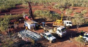

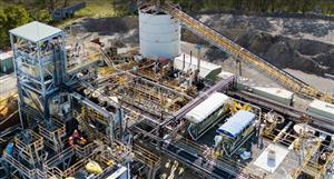


 (20min delay)