The invention discloses a pixel sound-generating unit and a manufacturing method thereof, a digital sound-generating chip and an electronic terminal, which are applied in the technical field of digital sound-generating chips to solve the problems of complex speaker structures and inconvenient installation. The pixel sound-generating unit includes a vibrating plate. The vibrating plate is provided with at least two dividing grooves arranged around it. Among the two adjacent dividing grooves, the end of one of them and the end of the other are along the center of the vibrating plate. The ray directions extending outward from the points are arranged in sequence to form an overlap in the direction of the surrounding arrangement. A diaphragm cantilever structure is formed between the overlapping dividing grooves, and the diaphragm, fixed part and diaphragm cantilever structure are integrated. structure. The digital sound-generating chip includes the pixel sound-generating unit mentioned in the above solution. The electronic terminal includes the digital sound chip mentioned in the above solution. The manufacturing method of the pixel sound-generating unit manufactures the pixel sound-generating unit mentioned in the above solution. The pixel sound-generating unit provided by the present invention is used to convert electrical signals into acoustic signals.
1. A pixel sound-emitting unit, including a vibration plate, characterized by:
The vibrating plate is provided with at least two dividing grooves arranged around it. Among the two adjacent dividing grooves, the end of one and the end of the other are along the direction outward from the center point of the vibrating plate. The extended ray directions are arranged in sequence to form an overlap in the direction of the surrounding arrangement, and a diaphragm cantilever structure is formed between the overlapping dividing grooves; the dividing grooves divide the vibration plate into parts located in the dividing grooves. The diaphragm in the surrounding area of the groove and the fixed part located outside the surrounding area of the dividing groove; the diaphragm and the fixed part are elastically connected through the diaphragm cantilever structure, and the diaphragm and the fixed part are elastically connected through the diaphragm cantilever structure. The fixed part and the diaphragm cantilever structure are an integrated structure.
2. The pixel sound unit according to claim 1, further comprising a back cavity and a base, the vibration plate is disposed on one side of the back cavity, and the back cavity is at least partially formed in the base .
3. The pixel sound unit according to claim 2, further comprising an electrode plate and a spacer, the base, the electrode plate, the spacer and the vibration plate being stacked in sequence;
A gap is formed between the electrode plate and the vibration plate by the spacer, the base has an opening, and the structure between the side of the diaphragm facing the electrode plate and the bottom of the opening forms a gap. The back cavity is described;
The electrode plate is provided with an array of through holes distributed in a position corresponding to the rear cavity, so that air can flow into the space between the electrode plate and the vibrating plate through the through holes to form air damping.
4. The pixel sound unit according to claim 1, wherein at least two of the dividing grooves form an annular structure, and one end of one of the dividing grooves is located inside the adjacent dividing groove in front of it, and the other end is located inside the adjacent dividing groove. The outer side of the rear adjacent dividing groove;
Alternatively, at least four of the dividing grooves are provided, and at least four of the dividing grooves form an annular structure, and one of the dividing grooves is located inside or outside of its front adjacent dividing groove and its rear adjacent dividing groove at the same time.
5. The pixel sound unit according to any one of claims 1 to 4, characterized in that the number of the diaphragm cantilever structures is at least two and they are symmetrically distributed.
6. The pixel sound unit according to any one of claims 1 to 4, wherein an arc-shaped groove structure for reducing stress concentration is provided at an end of the dividing groove.
7. The pixel sound unit according to claim 3, wherein the through holes of the electrode plate include round holes, elongated holes or square holes.
8. The pixel sound unit according to any one of claims 1 to 4, wherein the span of the diaphragm is 50 μm to 5000 μm, and/or the width of the cantilever structure of the diaphragm is greater than 1 μm.
9. The pixel sound unit according to any one of claims 1 to 4, wherein the cross-section of the diaphragm includes a circle, a rectangle or a regular polygon.
10. A digital sound-generating chip, characterized by comprising the pixel sound-generating unit according to any one of claims 1 to 9, the number of said pixel sound-generating units being multiple, and being distributed in an array or linear distribution.
11. The digital sound-generating chip according to claim 10, characterized in that the plurality of pixel sound-generating units are distributed in a rectangular array or a circular array.
12. An electronic terminal, characterized by comprising a terminal body and a digital sound chip according to claim 10 or 11, the digital sound chip being arranged on the terminal body.
13. A method of manufacturing a pixel sound-generating unit, characterized in that manufacturing the pixel sound-generating unit according to any one of claims 1 to 9 includes:
Design the size of the dividing groove according to the sound isolation requirements of the dividing groove on the vibrating plate in the pixel sound-generating unit;
Design the size of the diaphragm cantilever structure and the diaphragm according to the stiffness requirements of the diaphragm cantilever structure on the vibration plate and the resonance frequency requirements of the pixel sound unit;
According to the size of the dividing groove, the diaphragm cantilever structure and the diaphragm, the dividing groove is etched on the vibration plate to form a diaphragm located in the surrounding area of the dividing groove. The fixed part outside the surrounding area and the diaphragm cantilever structure connecting the diaphragm and the fixed part;
The electrode plate and the vibration plate of the pixel sound-generating unit are installed on the substrate, and the electrode plate and the vibration plate are energized with a gap between them.
14. The manufacturing method of the pixel sound-generating unit according to claim 13, characterized in that the size of the dividing groove is designed according to the sound isolation requirements of the dividing groove on the vibration plate in the pixel sound-generating unit; Based on the stiffness requirements of the upper diaphragm cantilever structure and the resonance frequency requirements of the pixel sound unit, the dimensions of the diaphragm cantilever structure and diaphragm are designed, specifically as follows:
Establish a flow-solid viscous boundary layer thickness model and a thermal boundary layer thickness model when air flows through the dividing groove, and design the size of the dividing groove according to the flow-solid viscous boundary layer thickness model and the thermal boundary layer thickness model, Ensure that the width of the dividing groove is smaller than the thickness of the flow-solid viscous boundary layer to achieve sound isolation;
Obtain the structural parameters and material parameters of the diaphragm cantilever structure, and establish a stiffness model of the diaphragm cantilever structure;
Obtain the structural parameters of the rear cavity of the pixel sound-generating unit, and establish an air stiffness model of the rear cavity of the pixel sound-generating unit;
Obtain the structural parameters of the diaphragm of the pixel sound-emitting unit, calculate the area of the diaphragm and establish a mass model of the diaphragm;
According to the stiffness model of the diaphragm cantilever structure, the rear cavity air stiffness model and the mass model of the diaphragm, a resonant frequency estimation model of the pixel sound-emitting unit is established, and the diaphragm cantilever is designed based on the resonant frequency estimation model. structure and dimensions of the diaphragm.
Technical field
The present invention relates to the technical field of digital sound-generating chips, and in particular to pixel sound-generating units and manufacturing methods thereof, digital sound-generating chips and electronic terminals.
Background technique
A speaker is a transducer device that can convert electrical signals into acoustic signals. Speakers are the basis for the production of audio and acoustic active noise reduction equipment. Therefore, the performance of speakers has a critical impact on the production of acoustic equipment. MEMS speakers (Micro Electro Mechanical System) are micro-electromechanical system speakers. Compared with traditional voice coil speakers, they have the advantages of good consistency, low power consumption, small size, and low price.
Currently commonly used MEMS speakers achieve simulated sound by pushing air through the movement of the diaphragm. Usually, MEMS speakers include a diaphragm and a spring that controls the reciprocating motion of the diaphragm. When using this structure, the diaphragm can vibrate under the action of the spring. To achieve sound transmission, however, this MEMS speaker has a complex structure and is inconvenient to install.
Contents of the invention
The purpose of the present invention is to provide a pixel sounding unit and its manufacturing method, a digital sounding chip and an electronic terminal, which are used to simplify the structure of the pixel sounding unit and make the installation of the pixel sounding unit more convenient.
In order to achieve the above objects, the present invention provides the following technical solutions:
A pixel sound-generating unit includes a vibrating plate. The vibrating plate is provided with at least two dividing grooves arranged around it. Among the two adjacent dividing grooves, the end of one of them and the end of the other are connected by the end of the vibrating plate. The ray directions extending outward from the center point are set in sequence to form an overlap in the direction of the surrounding arrangement. A diaphragm cantilever structure is formed between the overlapping dividing grooves. The dividing grooves divide the vibration plate into surroundings located in the dividing grooves. The diaphragm in the area and the fixed part located outside the surrounding area of the dividing groove; the diaphragm and the fixed part are elastically connected through the diaphragm cantilever structure, and the diaphragm, the fixed part and the diaphragm cantilever structure are an integrated structure.
Compared with the existing technology, in the pixel sound-generating unit provided by the present invention, the diaphragm is connected to the fixed part through the diaphragm cantilever structure, so that the diaphragm can reciprocate under the elastic action of the diaphragm cantilever structure. Using the above structure, the vibrator The diaphragm, fixed part and diaphragm cantilever structure are integrated structures, making the pixel sound unit simple in structure and easy to install. The diaphragm cantilever structure and diaphragm are formed by processing dividing grooves on the vibrating plate, making the diaphragm cantilever structure and diaphragm The production and processing of the pixel sound unit are more convenient, which in turn makes the production and processing of the pixel sound unit more convenient; when two adjacent dividing grooves overlap, the length of the diaphragm cantilever structure located between the two adjacent dividing grooves can be increased, making the diaphragm The vibration range is larger, ensuring that the diaphragm can elastically vibrate in the direction perpendicular to its outer surface.
Optionally, the above-mentioned pixel sound-generating unit further includes a back cavity and a base, the vibration plate is disposed on one side of the back cavity, and the back cavity is at least partially formed in the base. With this arrangement, the diaphragm can move and push air to achieve simulated sound production.
Optionally, the above-mentioned pixel sound unit also includes an electrode plate and a spacer. The base, the electrode plate, the spacer and the vibration plate are stacked in sequence; a gap is formed between the electrode plate and the vibration plate by a spacer, and the base has an opening. , the structure between the side of the diaphragm facing the electrode plate and the bottom of the opening forms a back cavity; the electrode plate is provided with an array of through holes distributed in the position corresponding to the back cavity, so that air can flow into the space between the electrode plate and the vibrating plate through the through holes. Create air damping. With this arrangement, the electrode plate and the vibrating plate form a flat capacitor, so that the diaphragm can vibrate under the action of the electric field formed by the electrode plate and the vibrating plate.
Optionally, in the above-mentioned pixel sound-emitting unit, at least two dividing grooves form a ring structure, and one end of a dividing groove is located inside the adjacent dividing groove in front of it, and the other end is located outside the adjacent dividing groove in the rear; or, There are at least four dividing grooves, and at least four dividing grooves form an annular structure, and one dividing groove is located inside or outside its front adjacent dividing groove and rear adjacent dividing groove at the same time. With this arrangement, the shape of the dividing groove is optimized, so that a diaphragm cantilever structure that meets the design requirements can be formed.
Optionally, in the above-mentioned pixel sound-emitting unit, the number of diaphragm cantilever structures is at least two, and they are symmetrically distributed. Such an arrangement can make the force on the diaphragm more uniform, the vibration more stable and controllable, and ensure that the pixel sound unit has good acoustic performance.
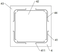
Optionally, in the above-mentioned pixel sound-emitting unit, the end of the dividing groove is provided with an arc-shaped groove structure for reducing stress concentration. Such arrangement can increase the strength of the end of the diaphragm cantilever structure and prevent the end of the diaphragm cantilever structure from breaking.
Optionally, in the above pixel sound generating unit, the through holes of the electrode plate include round holes, elongated holes or square holes. This arrangement facilitates air flow into the space between the electrode plate and the vibrating plate through the through hole to form air damping.
Optionally, in the above-mentioned pixel sound-emitting unit, the span of the diaphragm is 50 μm to 5000 μm, and/or the width of the cantilever structure of the diaphragm is greater than 1 μm. This arrangement allows the diaphragm to have a larger vibration range and good stiffness.
Optionally, in the above pixel sound unit, the cross-section of the diaphragm includes a circle, a rectangle or a regular polygon. This setting optimizes the shape of the diaphragm and makes the structure of the diaphragm more uniform.
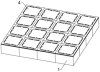
The present invention also provides a digital sound-generating chip, which includes the pixel sound-generating units described in the above solution. The number of pixel sound-generating units is multiple, and they are distributed in an array or linear distribution.
Compared with the existing technology, the beneficial effects of the digital sound-generating chip provided by the present invention are the same as those of the pixel sound-generating unit described in the above technical solution, and will not be described again here.
Optionally, in the above-mentioned digital sound-generating chip, multiple pixel sound-generating units are distributed in a rectangular array or a circular array. With this arrangement, consistent sound energy pulse output can be achieved through multiple pixel sound units, thereby improving the acoustic performance of the digital sound chip.
The present invention also provides an electronic terminal, including a terminal body and the digital sound chip described in the above solution. The digital sound chip is arranged on the terminal body.
Compared with the prior art, the beneficial effects of the electronic terminal provided by the present invention are the same as those of the digital sound chip described in the above technical solution, and will not be described again here.
The present invention also provides a method for manufacturing a pixel sound-generating unit. Manufacturing the pixel sound-generating unit described in the above scheme includes designing the size of the dividing groove according to the sound isolation requirements of the dividing groove on the vibrating plate in the pixel sound-generating unit; Based on the stiffness requirements of the membrane cantilever structure and the resonant frequency requirements of the pixel sound unit, design the diaphragm cantilever structure and the size of the diaphragm; according to the size of the dividing groove, diaphragm cantilever structure and diaphragm, etch the dividing groove on the vibration plate to Form a diaphragm located inside the dividing groove, a fixed part located outside the dividing groove, and at least two diaphragm cantilever structures connecting the diaphragm and the fixed part; install the electrode plate and the vibration plate of the pixel sound-generating unit on the base, so that the electrode plate energize the vibration plate and create a gap between them.
Compared with the prior art, the beneficial effects of the manufacturing method of the pixel sound-generating unit provided by the present invention are the same as the beneficial effects of the pixel sound-generating unit described in the above technical solution, and will not be described again here.
Optionally, in the above manufacturing method of the pixel sound unit, the size of the dividing groove is designed according to the sound isolation requirements of the dividing groove on the vibration plate in the pixel sound unit; according to the stiffness requirements of the diaphragm cantilever structure on the vibration plate and the pixel sound unit Resonant frequency requirements, design the diaphragm cantilever structure and the size of the diaphragm, specifically to establish the flow-solid viscosity boundary layer thickness model and thermal boundary layer thickness model when the air flows through the split groove, according to the flow-solid viscosity boundary layer thickness model Design the size of the dividing groove with the thermal boundary layer thickness model to ensure that the width of the dividing groove is smaller than the thickness of the flow-solid viscous boundary layer to achieve sound isolation; obtain the structural parameters and material parameters of the diaphragm cantilever structure, and establish the stiffness model of the diaphragm cantilever structure ; Obtain the structural parameters of the rear cavity of the pixel sound-generating unit, and establish the air stiffness model of the rear cavity of the pixel sound-generating unit; Obtain the structural parameters of the diaphragm of the pixel sound-generating unit, calculate the area of the diaphragm, and establish a mass model of the diaphragm; According to the diaphragm The stiffness model of the cantilever structure and the mass model of the diaphragm are used to establish the resonant frequency estimation model of the pixel sound unit, and the size of the diaphragm cantilever structure and diaphragm are designed based on the resonant frequency estimation model.
Description of the drawings
The drawings described here are used to provide a further understanding of the present invention and constitute a part of the present invention. The illustrative embodiments of the present invention and their descriptions are used to explain the present invention and do not constitute an improper limitation of the present invention. In the attached picture:
Figure 1 is a schematic diagram of a pixel sound-emitting unit when the diaphragm is a circular diaphragm in an embodiment of the present invention;
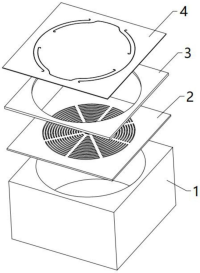
Figure 2 is an exploded schematic diagram of the pixel sound-emitting unit when the diaphragm is a circular diaphragm in the embodiment of the present invention;
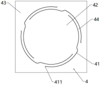
Figure 3 is a schematic diagram of a circular diaphragm in an embodiment of the present invention;
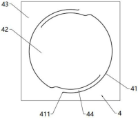
Figure 4 is a schematic diagram 2 of a circular diaphragm in an embodiment of the present invention;
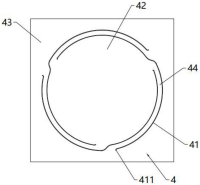
Figure 5 is a schematic diagram three of a circular diaphragm in an embodiment of the present invention;
Figure 6 is a schematic diagram 4 of a circular diaphragm in an embodiment of the present invention;
Figure 7 is a schematic diagram of the electrode plate in the pixel sound unit when the diaphragm is a circular diaphragm in the embodiment of the present invention;
Figure 8 is a schematic diagram of a pixel sound-emitting unit when the diaphragm is a square diaphragm in an embodiment of the present invention;
Figure 9 is an exploded schematic diagram of the pixel sound unit when the diaphragm is a square diaphragm in the embodiment of the present invention;
Figure 10 is a schematic diagram 1 of a square diaphragm in an embodiment of the present invention;
Figure 11 is a schematic diagram 2 of a square diaphragm in an embodiment of the present invention;
Figure 12 is a schematic diagram three of a square diaphragm in an embodiment of the present invention;
Figure 13 is a schematic diagram of the electrode plate in the pixel sound unit when the diaphragm is a square diaphragm in the embodiment of the present invention;
Figure 14 is a schematic diagram of a pixel sound unit when the diaphragm is a regular hexagonal diaphragm in an embodiment of the present invention;
Figure 15 is an exploded schematic diagram of the pixel sound unit when the diaphragm is a regular hexagonal diaphragm in the embodiment of the present invention;
Figure 16 is a schematic diagram of a regular hexagonal diaphragm in an embodiment of the present invention;
Figure 17 is a schematic diagram 2 of a regular hexagonal diaphragm in an embodiment of the present invention;
Figure 18 is a schematic diagram of a regular hexagonal electrode plate in an embodiment of the present invention;
Figure 19 is a schematic diagram of a digital sound chip in an embodiment of the present invention.
Reference signs:
1-base, 2-electrode plate, 21-round hole, 22-long hole, 3-spacer, 4-vibration plate, 41-dividing groove, 411-arc groove, 42-diaphragm, 43-fixed part, 44-Diaphragm cantilever structure.
Detailed ways
In order to make the technical problems, technical solutions and beneficial effects to be solved by the present invention clearer, the present invention will be further described in detail below with reference to the drawings and embodiments. It should be understood that the specific embodiments described here are only used to explain the present invention and are not intended to limit the present invention.
It should be noted that when an element is referred to as being "fixed to" or "disposed on" another element, it can be directly on the other element or indirectly on the other element. When an element is referred to as being "connected to" another element, it can be directly connected to the other element or indirectly connected to the other element.
In addition, the terms “first” and “second” are used for descriptive purposes only and cannot be understood as indicating or implying relative importance or implicitly indicating the quantity of indicated technical features. Therefore, features defined as "first" and "second" may explicitly or implicitly include one or more of these features. In the description of the present invention, "plurality" means two or more than two, unless otherwise explicitly and specifically limited. "Several" means one or more than one, unless otherwise expressly and specifically limited.
In the description of the present invention, it should be understood that the orientation or positional relationship indicated by the terms "upper", "lower", "front", "back", "left", "right", etc. are based on those shown in the accompanying drawings. The orientation or positional relationship is only for the convenience of describing the present invention and simplifying the description. It does not indicate or imply that the device or element referred to must have a specific orientation, be constructed and operated in a specific orientation, and therefore cannot be understood as a limitation of the present invention.
In the description of the present invention, it should be noted that, unless otherwise clearly stated and limited, the terms "installation", "connection" and "connection" should be understood in a broad sense. For example, it can be a fixed connection or a detachable connection. Connection, or integral connection; it can be a mechanical connection or an electrical connection; it can be a direct connection or an indirect connection through an intermediate medium; it can be an internal connection between two elements or an interaction between two elements. For those of ordinary skill in the art, the specific meanings of the above terms in the present invention can be understood according to specific circumstances.
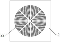
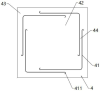
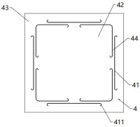
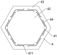
Please refer to Figures 1 to 18. The pixel sound generating unit provided by the embodiment of the present invention includes a vibrating plate 4. The vibrating plate 4 is provided with at least two dividing grooves 41 arranged around it. In the two adjacent dividing grooves 41, The end of one of them and the end of the other are sequentially arranged along the ray direction extending outward from the center point of the vibrating plate 4 to form an overlap in the direction of the surrounding arrangement. The overlapping dividing grooves 41 form a The diaphragm cantilever structure 44, the dividing groove 41 divides the diaphragm 4 into the diaphragm 42 located in the surrounding area of the dividing groove 41 and the fixed part 43 located outside the surrounding area of the dividing groove 41; the diaphragm 42 and the fixed part 43 The diaphragm cantilever structure 44 is elastically connected, and the diaphragm 42 , the fixing part 43 and the diaphragm cantilever structure 44 are an integrated structure. In this embodiment, it is preferred that the substrate 1 is a silicon substrate 1, the material of the vibration plate 4 is silicon material, and the preferred pixel sound-emitting unit is a MEMS speaker, a MEMS speaker (Micro Electro Mechanical System), that is, a micro-electromechanical system speaker. Compared with the traditional voice coil type The speakers have the advantages of good consistency, low power consumption, small size, and low price.
It can be seen from the structure and specific implementation process of the above-mentioned pixel sound unit that the diaphragm 42 is connected to the fixed part 43 through the diaphragm cantilever structure 44, so that the diaphragm 42 can reciprocate under the elastic action of the diaphragm cantilever structure 44. Using the above structure , the diaphragm 42, the fixed part 43 and the diaphragm cantilever structure 44 are integrated structures, making the pixel sound unit simple in structure and easy to install. The diaphragm cantilever structure 44 and the diaphragm 42 are formed by processing the dividing groove 41 on the vibrating plate 4 , making the production and processing of the diaphragm cantilever structure 44 and the diaphragm 42 more convenient, thereby making the production and processing of the pixel sound unit more convenient; when two adjacent dividing grooves 41 overlap, an additional number of adjacent dividing grooves 41 can be added. The length of the diaphragm cantilever structure 44 between them makes the vibration range of the diaphragm 42 larger, ensuring that the diaphragm 42 can elastically vibrate in the direction perpendicular to its outer surface. In addition, the diaphragm cantilever structure 44 can also suppress the diaphragm. 42 moves in the horizontal direction to ensure the stability of the vibration of the diaphragm 42, and at the same time can play a role in sound isolation and improve the acoustic performance of the pixel sound unit; the dividing groove 41 can also circulate the air on both sides of the vibration plate 4 to balance the vibration plate 4The air pressure on both sides ensures the stability of the vibration of the diaphragm 42.
It should be understood that at least two dividing grooves 41 divide the diaphragm 4 into a diaphragm 42 located within the surrounding area of the dividing groove 41, a fixed part 43 located outside the surrounding area of the dividing groove 41, and a connecting diaphragm 42 and the fixed part. The diaphragm cantilever structure 44 of 43, that is, the dividing groove 41 is open on both sides in the direction perpendicular to the outer surface of the diaphragm 4, so as to divide the diaphragm 42 separated from the fixed part 43 on the diaphragm 4, and the dividing groove 41 The diaphragm 4 is divided into three parts: the diaphragm 42, the diaphragm cantilever structure 44 and the fixed part 43. The diaphragm 42 is connected to the fixed part 43 through the diaphragm cantilever structure 44; at least two dividing grooves 41 are arranged around it, which means at least The two dividing grooves 41 are arranged around the diaphragm 42 and surround the diaphragm 42 .
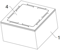
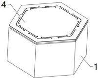
As a possible implementation, the pixel sound-emitting unit also includes a back cavity and a base 1 , the vibration plate 4 is disposed on one side of the back cavity, and the back cavity is at least partially formed in the base 1 . With this structure, the diaphragm 42 can move to push air to achieve simulated sound production.
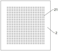
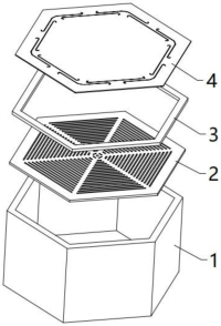
In some embodiments, the pixel sound unit also includes an electrode plate 2 and a spacer 3. The substrate 1, the electrode plate 2, the spacer 3 and the vibration plate 4 are stacked in sequence; the spacer 3 is between the electrode plate 2 and the vibration plate 4. The intervals form a gap, the base 1 has an opening, and the structure between the side of the diaphragm 42 facing the electrode plate 2 and the bottom of the opening forms a back cavity; the electrode plate 2 is provided with an array of through holes distributed in the position corresponding to the back cavity to facilitate air circulation. The air flows into the space between the electrode plate 2 and the vibrating plate 4 through the through hole to form air damping. With this structure, the electrode plate 2 and the vibrating plate 4 form a plate capacitor, so that the diaphragm 42 can vibrate under the action of the electric field formed by the electrode plate 2 and the vibrating plate 4 .
In this embodiment, the electrode plate 2 includes a round hole 21, a long hole 22, or a square hole, so that air can flow into the space between the electrode plate 2 and the vibrating plate 4 through the round hole 21, the long hole 22, or the square hole to form air damping to ensure that the electrode plate 2 An electric field that controls the vibration of the diaphragm 42 can be formed between the diaphragm 42 and the diaphragm 4. For example, the structure of the electrode plate 2 when the diaphragm is a circular diaphragm is shown in Figure 7, and the electrode plate is when the diaphragm is a square diaphragm shown in Figure 13. 2 and the structure of the electrode plate 2 when the diaphragm shown in Figure 18 is a regular hexagonal diaphragm; in this embodiment, the thickness of the electrode plate 2 is greater than 1 μm, ensuring that holes can be drilled on the electrode plate 2, preferably about 6 μm , when the round hole 21 is provided on the electrode plate 2, the diameter of the round hole 21 is less than 10 μm to ensure that air can circulate and the plurality of round holes 21 can be spaced apart, preferably about 4 μm. When the long hole 22 is provided on the electrode plate 2, The width of the long holes 22 is less than 10 μm to ensure that air can circulate and the plurality of long holes 22 can be spaced apart, and is preferably about 4 μm.
The shape of the through holes of the electrode plate 2 in this embodiment is not limited to round holes 21, elongated holes 22 and square holes, and can also be through holes of other shapes. The spacer 3 is used to create a gap between the electrode plate 2 and the vibration plate 4 to form air damping. The spacer 3 is preferably a spacer plate with an annular structure. The spacer plate is arranged at the circumferential edge position of the electrode plate 2 and the vibration plate 4 . The pixel sound-emitting unit is provided with a base 1, an electrode plate 2, a spacer plate, and a vibration plate 4 stacked in sequence.
During use, the electrode plate 2 and the vibrating plate 4 are energized to generate an electric field, and the diaphragm 42 can vibrate relative to the fixed part 43 under the action of the electric field to realize sound transmission, so that the pixel sound-generating unit can work normally. The pixel in this embodiment The sound-generating unit is a capacitive speaker composed of an electrode plate 2 and a vibrating plate 4. Compared with the dynamic speaker in the prior art, the pixel sound-generating unit of this embodiment has a simple structure, high sound quality and good sound effect. The diaphragm 42 has a large area and The high resonant frequency improves the acoustic performance of the pixel sound unit. The gap between the electrode plate 2 and the vibration plate 4 can form air damping between the electrode plate 2 and the vibration plate 4, ensuring that the electrode plate 2 and the vibration plate 4 can form a flat plate. capacitor to control the movement of the diaphragm 42.
Of course, the pixel sound-generating unit may not be provided with the electrode plate 2 and realize the vibration of the vibration plate by implementing piezoelectric driving.
As shown in FIGS. 1 to 18 , in this embodiment, the cross-section of the diaphragm 42 includes a circle, a rectangle or a regular polygon. At this time, the diaphragm 42 has a symmetrical structure, and the shape of the diaphragm 42 is more uniform, ensuring that the diaphragm 42 The vibration is more stable and controllable, and the acoustic performance of the pixel sound unit is improved. The cross-sectional shape of the diaphragm 42 in this embodiment is not limited to circles, rectangles and regular polygons, and other shapes such as ellipses can also be used.
As a possible implementation manner, in this embodiment, at least two dividing grooves 41 form an annular structure, and one end of a dividing groove 41 is located inside the adjacent dividing groove 41 in front of it, and the other end is located in the adjacent dividing groove 41 in the rear. On the outside, at least two dividing grooves 41 form an annular structure means that at least two dividing grooves 41 are arranged sequentially along the circumferential direction and are connected end to end, and the front adjacent dividing grooves 41 refer to at least two dividing grooves 41 of the annular structure, where The preceding dividing groove 41 and the adjacent dividing groove 41 of one dividing groove 41 refer to the dividing groove 41 following one of the dividing grooves 41 among at least two dividing grooves 41 of the annular structure. The inner side of the dividing groove 41 refers to at least The inside of the surrounding area formed by the two dividing grooves 41 is the side close to the diaphragm 42 , and the outside of the dividing groove 41 refers to the outside of the surrounding area formed by at least two dividing grooves 41 , that is, the side close to the fixing part 43 On the other hand, with this structure, a small number of dividing grooves 41 can be used to form a ring-shaped structure that meets the requirements, that is, the diaphragm 4 is divided into the diaphragm 42 located in the surrounding area of the dividing groove 41, and the diaphragm 42 located in the surrounding area of the dividing groove 41. The fixed part 43 outside the area and the diaphragm cantilever structure 44 connecting the diaphragm 42 and the fixed part 43 make the structure of the diaphragm 42 simpler and the processing more convenient.


 (20min delay)