hi a long read from mercury at sh@re screen By Anthony Short
The purpose of this series of articles is to provide the reader with a basic understanding of the oil industry and the terminology used. I am a director with an oil company who is required to interpret 'tech speak' and put it into normal language. I intend to pursue this objective in the articles that follow. Should there be any specific areas that you would like addressed, please put the questions to the editor and I will answer as many as possible.
The word petroleum comes from two Latin words meaning rock and oil. People gave it this name because they first found it seeping up from the earth through cracks in surface rocks. Today, petroleum is often referred to simply as oil, and most of it is found in rocks beneath the earth's surface.
Before about 1900, petroleum prospectors could do little more than look for oil seepages and hope for luck. Their equipment consisted chiefly of a pick, a shovel, and possibly a divining rod, a forked stick that some people believed could magically locate oil or water. During the 1900's however, petroleum exploration developed into a science. Today, prospectors use a variety of complicated instruments and are likely to be oil geologists or geophysicists.
In order for a commercial deposit of oil or gas to be found, (and these are not all that common), there must be three conditions present :
Source rock
A separate subsurface reservoir
A trap on the reservoir
Source rock is where the oil is generated from, the source is the organic matter that is buried and preserved in ancient sedimentary rocks. These rocks contain sands and muds and also dead plant and animal material.
The most common oil bearing sedimentary rock is black shale. The shale is deposited as organic muds and then gradually covered with other layers of sands, and as it is buried deeper, the temperature rises. The deeper the depth the higher the temperature. The minimum temperature for the formation of oil is about 65 degrees C, and the maximum temperature where oil production ends is 150 degrees C.
The zone where oil is generated is called the oil window. This window is between 2130 meters and 5500 meters. Heavy oil called immature oil, is generated at lower temperatures in the window and at higher temperatures cooked oil or carbon is generated.
At temperatures above 150 degrees C, crude oil is changed into graphite and natural gas.
Reservoir Rock is the rock formations through which oil and gas travels once it is formed. Oil and gas being light in density, will rise through fractures or gaps left between the reservoir rocks. Reservoir rock is a sedimentary rock layer, much like sand grains on the beach or in a river channel that contains billions of tiny spaces called pores.
The larger the pore, the more permeable the structure is said to be, or the easier the oil and gas can move through the structure. The porosity of a reservoir is the percentage volume of the rock that is not occupied by solids.
Porosity is measured with an instrument called a porosimeter. If the porosity of the structure is low, typically 8-10% for sandstones, the reservoir would not pass the porosity cut off and usually the well would not be completed.
Permeability. The other measure relevant to the reservoir is the permeability and is a measure of the ease with which the fluid can flow through the rock. Permeability is measured with an instrument called a permeameter and is measured in millidarcies (md). The higher the permeability measurement, the easier fluids will flow. A reservoir is said to have good permeability at around 10-100 millidarcies.
Tight sands. Reservoirs which have permeabilities of 5md or less are referred to as tight sands. Any fluid or gas can move through these pores or migrate, and as a result oil can over time travel great distances until it encounters a trap. If there is no trap present the gas or oil will flow to the surface as a gas or oil seep, and be lost.
A Trap is a high point in the reservoir rock where the oil or gas is stopped by an impermeable barrier and concentrated or accumulated. The gas being the lightest goes to the top of the trap to form the free gas trap. The oil gases to the middle of the trap in the saturated pool, and salt water goes to the bottom and completes the trap.
Oil - Water Contact. The contact point between the salt water and the oil is known as the oil - water contact. For a trap to be effective it must have four sided closure, meaning that the trap must be sealed on all four sides to hold the petroleum. A cap rock must overlie the reservoir and is impermeable, and acts as a seal to prevent the oil or gas leaking to the surface.
Two common seals are shale's or salt layers.
The Oil Field is then defined as the surface area directly above one or more producing reservoirs.
Types of Traps. There are many types of traps, the most common being structural traps, which are formed when the reservoir rock is deformed (broken or fractured and/or folded).
Dome or Anticline. One type of structural trap is a natural arch in the reservoir rock, called a dome or anticline. A good example of a large anticline is the Powder River basin in Wyoming which was drilled in 1907. When a surface seap was discovered, the field produced 766 million barrels (bbls) of oil and 750 billion cubic feet (Bcf) of gas.
Strategraphic Traps. Other common traps are strategraphic traps which are angular unconformities in the reservoir rock, or where a reservoir rock is cut off by a seal and oil is stopped from migrating further in along the reservoir. These reservoirs can be old marine reef structures which have been buried under sediments until they enter the oil window and the required temperature to form oil.
Obviously traps come in all shapes, sizes and combinations and have great names like bald headed structures and the like. One of the great traps of all time was the Spindletop salt dome, the first salt dome drilled in 1901 by Colonel Drake. The well blew in as the worlds great high pressure gusher at a rate of 75,000 barrels (bbls) of oil per day to a height of 60 meters. In nine months, 64 more wells were drilled in the dome with the dome yielding 17.5 million barrels in 1902, and eventually produced 130 million barrels of oil. The oil industry was born and many companies were formed, the greatest being Standard oil.
PART 2
Petroleum is found on every continent and beneath every ocean. But present-day techniques enable petroleum engineers to recover (bring to the surface) only about a third of the oil in most deposits. These recoverable amounts of petroleum are called reserves.
Early oil finding techniques relied on the surface demonstrations of oil escaping through to the surface in what were called oil seeps. The purpose of drilling was to increase the flow of oil to the surface, usually surface oil is degraded to heavy oil as the lighter oils are degraded by evaporationand bacteria and are represented at the surface as tars or asphalts.
In the early 1900s it was accepted that oil accumulated in high areas in reservoir rocks such as domes or anticlines. This theory was finally accepted as oil companies hired geologists to perform ground truthing by identifying and mapping sedimentary rocks at surface.
With the use of aircraft and in the 1970s satellites have been used to map large areas of the earth's surface. This activity provided good early identification and were followed up by geological reasoning. This involved the correlation of drilling results from successful wells with other drilling activities to create a correlation in the subsurface maps.
The correlation factors are the matching of rock structures starting with the marker bed, usually a distinctive rock layer that is easily identified as being consistent. Once this layer is identified, a cross section of the subsurface structure is made using the well log.
The well log is the record of rocks made from the drill core and is used to compare the geological structures between wells. These can be made through using structural cross sections using modern sea level as the marker, or stratigraphic cross sections using the marker bed in each well as the key structure to map the comparisons between wells. Usually companies will drill tight holes or stratigraphic wells to assist in the mapping of an area before commercial drilling commences.
In addition to drilling, the use of geochemical techniques have been developed to identify traces of hydrocarbons in the surface and subsurface waters. These activities use such instruments as gas chromatographs and are used to identify the hydrocarbon halo or traces of oil that surround a seep.Boats and planes can be fitted with sniffers to detect seeps at sea or in waters surrounding or in drill locations or in remote areas.
An additional method is vitrenite reflectance, which is a method used to determine the maturity of source rock. Vitrenite is a type of organic matter found in shale, the source rock is polished and examined under a reflectance microscope. The more mature the source rock, the higher the percentage of light reflected.
A common technique is to follow a play which is a trap, reservoir rock and seal combination that has previously shown to contain a commercial oil field. A company could then follow the trend or fairway in the area to identify additional fields in the area. Once the drill area has been identified and a drill location identified, the area can be designated a prospect. The most modern techniques used are called geophysics, which is the use of physics and mathematics to the study of the earth.
Geophysicists use three surface methods:-
Gravity,
Magnetics and
Seismic to explore the subsurface.
Gravity and magnetics are measured using gravity meters or gravimeter which measures the acceleration of the earth's gravity at specific locations, the gravity meter measures in milligals and is used to identify the relative mass of rocks at the surface. Heavy rocks such as the core of a dome or anticline can be detected as higher than normal gravity measures. Low readings on a gravimeter may show the presence of possibly oilbearing, porous layers of rock. Gravimeters are particularly effective in detecting salt domes because salt decreases the pull of gravity more than most rocks do.
The magnetometer
Magnetics are measured using a magnetometer which can be mounted on a truck or used in an aircraft to perform an aeromagnetic survey. The surveys measure the earth's magnetic field and measures the variation in the elevation of basement rock and can be used to estimate the thickness of sedimentary rocks filling a basin and to locate faults. A subsurface salt dome can be identified as a surface anomaly of relative low gravity and magnetics because the salt is light in density.
The seismograph
The most intensive search tool is seismic, which was first used in 1928 in Oklahoma. Seismic uses sound energy that travels through the subsurface rocks, reflects off subsurface rock layers and returns to the surface to be recorded. Seismic equipment used in oil and gas exploration is similar to a depth sounder on a boat.
On land the sound sources are explosives which are planted in solid rock. The other seismic source commonly used is a vibrator truck, or a truck fitted with hydraulic motors fitted to a pad, which is lowered to the ground and shakes the ground to create a sound wave which can be recorded through a geophone.
The seismic process is used to record the density differences in deep rock layers depending on how quickly the sound waves are reflected back. If the sound reflection has a low return velocity, or a bright spot, the sound wave has reflected of a slow velocity area such as gas or sedimentary rock. If the reflection is off an anticline, it will represent as a flat spot on the seismic trace.
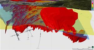
The most recent innovation in seismic technology is 3-D seismic which gives a three dimensional image of the subsurface increasing the interpretative capacity of the subsurface geology. Three-D seismic has resulted in far greater accuracy in the drilling what previously would have been high risk locations.
In the process of conducting the seismic process, exploration companies need to go through the process of leasing mineral rights over land to be drilled. This, in most areas, results in the negotiation of the royalty fee to be paid to the land owner (in our experience in Texas this usually runs at 20%).
This royalty fee gives rise to the distinction between the working interest owner who owns the gross revenue on a property prior to royalty or a net revenue interest which is the revenue interest in the property after royalty. Prior to a drilling contract being entered into working interest positions and net revenue positions are set and drilling contracts set.
It is not unusual for properties prior to production to be promoted out or sold down on 8ths basis or an 8/8ths share would be a 100% interest and divisions would be made on percentages of the 8ths share. Historically I believe the basis of the 8ths share is linked to the splitting of the share of a fishing catch between members of a crew (8 members) depending on seniority.
PART 3 Land Based Drilling Programme
Drilling remains the only true way to prove whether oil or gas in commercial quantities exist in a prospect area. However, from the onset it is important to understand that drilling for petroleum is nearly always an enormous gamble.
Most geological and geophysical studies indicate the places where petroleum might have accumulated. However, there is less than a 10 percent chance that oil is actually present in those places. There is only a 2 percent chance that it is present in those places in commercially useful amounts. Many dry holes may be drilled before a producing well is brought in and the oil begins to flow.
The drilling programme usually begins with an authorisation for fixed expenditure (AFE) which should incorporate all the costs to complete the well.
This section will deal with land based drilling only.
Spudding
Site preparation starts with the digging of a reserve pit to hold unneeded drilling mud. The start of drilling a well is called spudding in which is usually done with a large diameter shallow hole. A conductor casing is then cemented into place. The casing stabilises the top of the well and provides the attachment for blowout preventers.
Wildcat Wells
A well being drilled in a new field is called a wild cat if the location is 3 kms from any known production. Once a discovery has been made a series of stepout wells can be drilled to all four sides of the discovery.
Rotary Rigs
The most common rig in use today is the rotary drilling rig; this rig was introduced in the period between 1895 and 1930. This type of rig rotates a long length of steel pipe (the drill string) with a cutting bit on the end of it to cut a hole called a well bore. The rotary table of the rig is located in the derrick floor or tower floor and is rotated to the right through a length of six sided high grade steel called the Kelly. Below the Kelly is the drill pipe.
Drill pipe
The Drill Pipe is heat treated alloy steel and comes in lengths of 5.5 to 14 metres but are commonly 9 metres long and range in outer diameter from 7 to 14cm. Drill pipe is added to the drill string below the Kelly in a process called making a connection. To achieve this the drill string is raised using elevators and held with tongs and a spinning wrench to stop the string from falling down the hole. A new drilling connection is then made and the drill string lowered in to position.
The section of dril lstring below the drill pipe is called the bottom hole assembly. Below the drill pipe are thick walled heavy duty pipes called drill collars. These collars are heavy, thick-walled pipe, usually steel, used between the drill pipe and the bit in the drill stem to weight the bit in order to improve its performance. They are designed to put weight on the bottom of the drill string to prevent the drill pipe from kinking and breaking.
The Drill Bit
The business end of the drill string is the drill bit. Around 98% of rotary wells drilled are drilled with a rotary cone bit. The tricone bit has three rotating cones attached to three legs. The body of the bit is made of heat treated alloy that has been welded together. Each leg has a jet and channel for drilling mud to flow through and the cones are pin mounted on each leg and rotate on sealed self lubricating bearings. Each cone has several rows of protruding teeth that are designed to crush chip and flake away rock as the bit is rotated.
The teeth on the bit can have buttons of tungsten carbide inbedded in the cone if the rock types are harder. Very hard rocks are drilled using a diamond bit made of solid steel with no moving parts. Normally the bit is rotated at 50 - 100 rpm, generally faster at shallower depths and the pressure exerted on the bit down hole is about 3000-10000psi per inch.
Normally a tricone would wear out after 8-200 hours of rotation with an average bit lasting 40-60 hours depending on rock types. The changing of a bit is called making a trip where the drill string is pulled out of the hole, the bit changed and the drill string is put back in the hole for drilling to recommence.
Drilling Mud
The bit is cleaned cooled and lubricated while drilling by pumping drilling mud through the bit. The drilling mud is held in steel mud tanks on the surface and mixed with an agitator to a consistent quality. The mud is pumped down using a triplex pump, which drives the mud down on both strokes. The mud flows down the hole in the drill string and jets out through holes in the drill bit legs. The drilling mud picks up rock chips (cuttings) from the bottom of the well and flows up the well in the space between the drill string and the well walls.
At the top of the well the mud flows through blow out preventers along the mud return line and on to various screens to remove solids. Once separated the clean mud flows in to the mud tanks to recirculate down the well. Drilling mud is a mixture of clay weighting material and chemicals with either water (water based drilling mud), diesel oil (oil based drilling mud) or a mixture of oil and water (emulsion mud), the most common drilling mud is made from fresh water and bentonite clay.
The viscosity of the mud can be increase, by adding more clay. This process is called mudding up. Drill muds are described by their weight, fresh water weighing 8.3 pounds per gallon and an average mud weighs 9-10 pounds per gallon.
The mud properties are checked at surface regularly to ensure that the mud is circulating properly and that mud pressures are being maintained. Usually mud pressures are kept higher than the pressure in the sub-surface rock to keep water and gas out of the drill hole. If the pressure is less (or under balanced) than water, gas or oil can flow into the drill hole which can cause the well to cave in or slough in.
Blowout Preventers (BOPs)
The pressure of the mud can be increased if down hole pressures increase. However, if the pressure increases quickly, the hole may blow out (fluids rush to the surface unchecked). This occurrence is controlled by the blowout preventers (BOPs) which are safety devices for closing the well head. The BOPs are a series of rams that are designed to close over the well and cut across the pipe to cut off or kill the well preventing fluids from escaping.
Common problems
As in all operations, a number of common problems may be encountered. The prime objective is to complete a well to commercial production. The ratios for this in America are approx 13-1 and in Australia approx 60-1.
Plugged and Abandoned
The balance of the wells are dry holes which are then plugged and abandoned, i.e when they are deemed to have ceased producing oil or gas from a well or when it becomes unprofitable. A wildcat may be abandoned after it has been proved non-productive. Sometimes, before a well is abandoned, some of the casing is removed and salvaged.
Usually, one or more cement plugs are placed in the borehole to prevent migration of fluids between the various formations. In many states, abandonment must be approved by an official regulatory agency before being undertaken.
Loss of the Drill String
One of the most common problems is the loss of the drill string down hole. If this occurs, the remaining drill string is pulled from the hole and special tools are lowered down the hole to fish for the broken section. These tools can be magnets or impression blocks to attach to and remove the section from the hole.
Loss of Circulation.
Another common occurrence is the loss of circulation or drop in mud pressures down hole. During the drilling process, mud can be forced into the permeable rocks down the hole and not return to the surface. This is usually corrected by adding fibres flakes or mixtures to seal off the formation. An abnormal high pressure caused by an unexpected kick in down hole pressure, is usually caused by a flow of gas, oil, or water into the drill hole. As the water or oil flows in to the well the drill mud dilutes and the diluted drilling mud is called gas cut, water cut or oil cut depending on the fluid and the amount of dilution.
There are a wide variety of other problems associated with drilling wells and the risks are high and far from certain. In the next section we will look at the evaluation techniques used to determine whether a well should be shut in or completed.
PART 4 - Evaluation Techniques Determine Whether A Well be Shut In Or Completed.
After a well has been drilled and tested there are only two options to complete or to plug and abandon the well. As the completion of a well can cost as much as the drilling of the well, the analysis or evaluation of the well becomes a critical process. The evaluation is based primarily on well logs, the well logs describe the rocks and their fluids through which the well has been drilled. As a result there are a number of logs and we shall look at he more common logs and the information they convey.
The primary log used is the sample or lithographic log which is a physical description of the rocks through which the well is drilled. The log described the rock types drilled through, mapped against the depth that the rocks are encountered at. The primary information source for the logs are the well cuttings or small rock chips that are made by the drill bit and flushed up the well by the drilling muds. The cuttings are examined through a microscope and if oil samples are present they can be identified with an ultraviolet light. Different oils with varying specific gravities fluoresce with different colours under a UV light.
The most accurate source of information on reservoir characteristics is a drill core. A core is taken by using a coring bit which is solid metal with industrial diamonds inserted for cutting. A cylinder of rock is left to pass up in to the hollow of the drill bit with the core sample retained in the drill barrel located above the bit. To recover the drill core the drill string is tripped regularly and the core removed. Usually because of the cost of coring only the reservoir interval is cored. Usually rocks that are highly fractured or very porous are not retained in the core, therefore loss of core can indicate good reservoir rock. A faster and less expensive way of taking samples is sidewall coring. This occurs after the well is drilled, a side wall coring devise is lowered down the well to the rock interval to be sampled. A percussion sidewall coring tool commonly has 30 small core tubes called bullets with explosive charges behind them. These are detonated with the bullets shot into the side wall to take samples.
There are a number of logs taken during the drilling program - in no particular order these are :
Driller's log - taken by the driller and can be subjective depending on the level of skill and experience of the driller and the rock types he is drilling through.
Drilling Time log - measures the rate of penetration of the drill bit (ROP) this is usually recorded in meters or feet per second. As long as the drilling parameters stay the same ( revolutions per minute, weight on the bit and bit type ) the only variation in drilling rate is caused by variations in rock type. Sandstones have the fastest drilling rate, shales are intermediate and carbonates the slowest. A change in drilling rate is called a drilling break and usually occurs as the bit penetrates the top of a different rock layer. Drilling breaks usually occur as the bit encounters more porous zones which are easier to drill.
Mud Log - is a chemical analysis of the drilling mud and well cuttings for traces of subsurface gas and oil as the well is being drilled. The drilling mud is sampled from the shale shaker or mud screens. A mud log will have the depth of the well, rate of penetration and a hydrocarbon evaluation that shows the amount of gas and oil detected in the drilling mud. Oil or gas in the drilling mud is called oil-cut and gas-cut mud. Any oil or gas above the background levels is called a show.
Wireline Well Logs - these were first developed by the French in the 1920's. The log is made after the well is drilled by lowering a sonde or tool down the well on a wireline. The sonde is a torpedo like device that contains instruments that measure the electrical acoustic and radioactive properties of the rock and their fluids as well as measuring the well bore with arms extended from the sides of the sonde. These properties are transmitted up a cable to the field truck and printed out. The wire line log has three tracks depending on the log, each track carries different information but usually this includes the depth, the property of the rocks and the fluids in the well and the diameter of the well. A scale of measurement is located at the top of each line a variation of the track from one side to another is called a kick. Most logs are run on an open hole basis where the log is run into a well with bare rock walls. Cased hole logs are run in a well in which the casing has been cemented in.
The measurements taken are usually as follows :
Track 1 spontaneous potential, natural gamma ray and caliper logs.
Track 2 and 3 resistivity, formation density, neutron porosity, and sonic logs.
The measures used for logs are various the most common are :
Electrical logs measure the resistivity or conductivity of rocks and fluids by passing an electrical current through the rocks. Resistivities measured are short term and long term based on the distance that the electrodes are apart. Depending on the level of resistivity it can also be ascertained what fluids are present in the pores of the rocks. Salt water has a low conductivity and therefore has low to moderate resitivity, oil and gas have very high resistivity. Oil and gas cannot be differentiated on the log however a kick in the log will indicate the oil water contact point. The level of oil saturation in the reservoir can also be determined by the level of resistivity the higher it is the higher the level of saturation. Most rocks and reservoir types have characteristic signatures on the logs which allow the interpretation of the rock types and fluids present and saturation of fluids in the reservoir.
Induction logs are run in wells drilled with oil based muds which inhibits the conduction of electricity. The log uses coils in the sonde to focus and induce electrical current in the rocks in the well bore and achieves the same measurements as the wireline log.
Natural Gamma Ray Logs measure the natural radioactivity of rocks in the well. Of the three sedimentary rocks only shale, which contains potassium, is radioactive. Therefore the trace shales hot kick the trace to the right while sand and limestones kick to the left. The amount of shale in the formations can be calculated from the level of radiation detected on the log.
Neutron Porosity logs are used to measure the porosity of the rocks in the well. This is done by bombarding the rocks adjacent to the well bore with high speed neutrons as the tool is raised in the well. If the high speed neutron hits a large rock atom, the neutron is bounced back with almost no loss in energy indicating a tight structure. The more slow neutrons emitted the more porous the formation. The level of bounce back can also measure the level of hydrogen present in the rocks and therefore be used to measure the level of water, oil or gas present in the structure.
Formation density or Gamma - Gamma logs are also used to measure porosity. The rocks are bombarded by gamma rays. If the Gamma ray collides with large rock atom, part of the gamma ray is absorbed and a weaker gamma ray is scattered back and hence denser rocks and less porosity. Gamma rays are not affected by small atoms such as hydrogen. The porosity of the rocks can be calculated from the density of the rock formations as seen in the level of gamma rays absorbed.
Caliper logs measure the diameter of the well and assume that softer rocks will break away from the drill hole and leave wider openings in the well bore. Harder rocks will retain their form and have a diameter the same as the drill bit.
Sonic or Acoustic velocity logs measure the velocity with which sound travels through the rock formation. The porosity of the rocks can be calculated by the acoustic qualities of the rocks, shales having the lowest acoustic velocities and limestones and dolomites the highest.
Drill stem test are similar to a temporary completion of the well and are run with the well still full of drilling mud and arealso run if the logs indicate a potential reservoir. The DST is run to evaluate the reservoir. If the formation to be tested is in the mid part of the well bore, the section is isolated with packers to seal off the area above and below the drill stem to eliminate the pressure of the drill mud. As the pressure is dropped, oil, gas or water can flow from the rock formation into the well bore and up the drill stem and can be measured at surface. The DST measures the pressure of the fluid flow and, depending on the pressures and flows the reservoir pressure and permeability can be measured. DST's can take from 20 minutes to several days depending on the formations present and the amount of information required.
All these tests are designed to take the guess work out of identifying the porosity and level of saturation of the well with oil or gas, given high level of saturation and good porosity the well will usually be completed.
PART 5- Well Completion.
After a well is drilled and tested there are two options, to plug and abandon the well, or to complete the well by setting pipe.
All wells whether drilled and non commercial or finally depleted must be plugged and abandoned (p&a). The procedure is required by law to prevent saltwater pollution from the well and involves the cementing of the bore hole. Where possible casing is extracted from the well and mechanical plugs inserted to control the depth of the cement. The drill hole is then filled with cement and covered over.
A far more satisfying process is the completing of a well, this is usually tied to the setting of pipe. The pipe is casing or thinned walled pipe commonly 14-35 cm. The casing is joined to make a casing string and run into the drill hole, cement or slurry is then pumped into the space between the drill hole walls.
There are a wide variety of cements available depending on corrosion pressures and types of reservoirs being cemented, but the aim in all cases is to provide a channel for the oil or gas to flow through to the surface. Once the well casing is in place an intermediate or protection casing can be run in to isolate problem zones in the well such as high pressure area, lost circulation areas or high salt zones.
The final string put in place is the production or oil string that runs to, or through, the producing zone. It is typically 14 cm and can be substituted with a linear string to save money. The linear string unlike the casing never runs all the way to the surface and is suspended in the well and cemented in.
The bottom of the well can be completed either with an open hole or cased hole completion. A top set, open hole or barefoot completion is made by drilling down to the top of the producing formation, the well is cased and then drilled through the producing formation leaving the bottom of the well open. This type of completion relies on the formation being hard so that soft sands do not flow back up the pipe.
When both the casing strings have been set in place, the casing is perforated by shooting holes through the casing to allow the oil or gas to flow in to the production string. Early perforations were running perforating gun into the formation and firing steel balls through the casing into the formation. More commonly today, jet perforators are used that fire shaped explosive charges into the formation. Perforations are described in shots per foot or density and angular separation (phasing).
Once the perforations are completed, a tubing is run into the well to just above the bottom to conduct the water gas or oil to the surface. The tubing is suspended in the well and therefore can be removed and repaired if required. Once the tubing is in place a completion fluid, usually treated water, is pumped in between the casing and the tubing to prevent corrosion.
If the well has to be pumped, a down hole pump is placed at the bottom of the tubing string and the string anchored to the bottom of the casing. A tubeless completion runs the oil or gas up the casing string.
On the surface is the well head which is a permanent, large, forged or cast steel fitting at the top of the well. It is made up of a larger, lower casing head which seals off the hole in the casing strings. The casing head provides the connection between the casing and the blowout preventor stack or production equipment. All wells, once the production equipment is installed, are chocked off to control their flow rate and prevent the depletion of pressure in the reservoir. The chokes are valves that cause the fluid to flow through a small hole called an orifice.
Gas wells normally flow to the surface without assistance. Most oil wells in the early development of the industry were flowing wells and required the fitting of a Christmas tree or production tree to control the flow from the well. All Christmas trees have a master valve on the lower part to close off the well if required. Above that, the tree can have several wings depending on the number of producing zones in the well. At the top is usually a swab line to allow the lowering or wire line equipment down the well and a pressure gauge that measures tubing pressure.
In the USA 95% of wells do not have sufficient pressure to freeflow, and the oil has to be lifted to the surface using artificial lifting devices. The most common artificial pump is the sucker rod pump system. The sucker rod uses a downhole rod pump, a surface pumping unit and a sucker rod string that runs down the well to connect them. The sucker rod pump has a standing valve which consists of a ball, a seat and a cage. The ball allows the oil to flow up but not down the casing. Each upward stroke of the valve lifts oil up the tubing to the surface.
The surface pumping unit is most commonly a beam pumping unit with a steel beam called a walking beam that pivots up and down a bearing on top of a Samson post. The beam is driven by an electric motor, the motor is connected by a V belt drive to a gear reducer that controls the speed of the pump. On the other end of the walking beam is the sucker rod string.
Sucker rods are solid steel alloy rods 1 to 3 cm in diameter and usually 7.5 m long. Counterweights are used on the other end of the walking beam to counteract the weight of the rod string. A large curved head is used on the well side of the walking beam to keep the pull on the sucker rods vertical. Two wire ropes or bridals are used to connect the horse head to the sucker rod string. At the top of the sucker rod string is a polished rod or a smooth length of steel or brass that oscillates through a stuffing box, (a steel container on the well head that contains flexible material or packing cups to provide a seal around the polished rod ensuring that oil is not pulled on to the surface).
Other methods of lifting oil are to create a gas lift well where a compressed inert gas is injected into the well between the casings. The gas flows in to the tubing through gas lift valves where it mixes with the fluid lightening the liquid and forces the oil up the tubing string.
On deeper wells a submersible electrical pump is used. Once the oil is at the surface it is pumped through flow lines to a central processing unit. The combination of flow lines is referred to as the gathering system. At the central processing unit is a metal tank called a separator. The separator is made up of a number of sections that separates the liquid from the gas and then separates the oil from the water.
The most common is the free water knock-out operator which is vertical or horizontal and is used to separate oil and free water by gravity. Once the oil is separated, the oil is put in to a stock tank. These tanks are usually in sequence and are referred to as a tank battery. Tank batteries vary in size depending on the production rate of the field and the frequency that the tanks are emptied.
PART 6 - Final.
The production of oil and control of wells is usually the domain of the petroleum engineer. To bring a well into production, the drilling fluid is removed from the well with the use of a swabbing unit to pump the fluid out and to start the well flowing. Once the flow is established, the well pressure is measured at the top of the well and in the casing. Well tests are run regularly during the life of a well. The most common tests are the potential tests which determine the maximum gas and oil that the well can produce in a 24 hour period. A productivity test can be run to determine the effect of different production rates on the reservoir. The test is used to determine the absolute open flow rate of the well and the maximum production rate possible without damaging the reservoir. Other tests are used to determine the pressure and flow rates of a well (pressure transient testing), or the shut in bottom hole pressure (a drawdown test).
Once in production a well can have production logs run to establish if the well is having any problems. The logs run are :
Pulse neutron log which is used to find oil or gas hidden behind the casing
Tracer logs are used to detect fluid movement in the well
Continuous flow meter measure flow rates in the well at various depths
Packer flow meter uses a packer to close off the well at depth to measure fluid flows through the meter
Noise log uses a microphone to detect any sounds in the well
Manometer measures the pressure in a well at specific depths
Watercut meter measures the amount of water in the fluid
All the tests are designed to ensure that the well produces at the most efficient rate, if a well is produced too hard a rate, a well can cone out when water is drawn up in to the well bore. The aim is to achieve the maximum efficient rate to produce a well at which generally ranges from 3-8% of the recoverable oil or gas a year.
All wells go into a steady decline once they have started production until they pass their economic limit or can no longer be produced for a profit. To extract the maximum amount of product from a well, the well can be stimulated from time to time. Stimulation methods vary depending on the permeability of the reservoir. A well can be acidized by pumping acid down the well to dissolve limestone or waxes to increase permeability and flow rates. Inhibitors are used to protect casings and down hole equipment. In more drastic situations, the well is subjected to explosive fracturing. This is done by lowering a tin cylinder, (torpedo), filled with nitroglycerine down the well and exploded to open up fractures in the surrounding rocks. Frac jobs can also be done with fluids under high pressure being pumped down the well bore to fracture the reservoir rock. The fracture is then kept open by small spheres called proppants, usually sand or aluminium oxide pellets.
There are times during the life of a well when the well must be shut in for remedial work to restore or improve production, this process is called a workover. A workover rig, which is similar to a drilling rig, is used to pull the sucker rods from the well and to remove the tubing if required. The tubing is cleaned out to remove scale, which is usually deposits of calcium or crude waxes which have built up in the casing. While the casings are out, the well can be re-cemented and the bottom of the hole cleaned out and the well recompleted to produce from a different producing zone.
A well that is producing from its original reservoir is called a primary production well. Once the well has produced approximately 30% of the oil in place the primary production drive will be exhausted and to remove the balance of the oil, different oil recovery techniques are required. The most common recovery technique is to commence a water flood operation. This involves the injecting of water in to the depleted reservoir. The water sweeps through the formation pushing oil through the formation, towards the producing bore. Other techniques used to enhance oil recovery are :
Miscible gas drive, which involves injecting gas into the reservoir that then dissolves in the oil. The gas then pushes the fluid through the reservoir towards the producing well.
Chemical flood is a process in which different fluids are injected into the depleted reservoir in separate batches or slugs. The fluids each serve a different purpose. A micellar-polymer flood is used to condition the reservoir, next a surfactant fluid such as a detergent is injected to reduce the surface tension of the oil in the well. The next slug is water which has been thickened by polymers and pushes oil through the formation. These methods can recover about 40% of the remaining oil in the well.
Thermal recovery techniques use heat to make heavy oil more fluid for easier recovery. The heat transfer is achieved by pushing steam in to the reservoir to achieve a steam flood or steam drive and aims to assist in the recovery of an additional 25-60% of oil in situ.
Once a well has been subjected to secondary recovery techniques and is unable to be stimulated any more and has passed its economic limit, the well is plugged and abandoned and all useful equipment recovered.
So ends the life of a well and this series of papers. I hope that you have found them informative and of use in analysing announcements in the future.
Ends
Thought perhaps a few ofyou would like this
Mercury
HDR
hardman resources limited
uganda - why no logging?, page-8


Add to My Watchlist
What is My Watchlist?