WITH KUDOS AND THANKS TO
TOOL BOX
IMHO what a load of cods wabble,
They did not take into account the VELOCITY AND THE FOCAL POINT AND VECTOR OF THE INITIAL IMPACT,
If you speed up a soft fly fast enough you could shoot it though a human body.
Useful equations related to acceleration, average velocity, final velocity and distance traveled
Average Velocity
va = (v1 + v0) / 2 (1)
where
va = average velocity (m/s)
v0 = initial velocity (m/s)
v1 = final velocity (m/s)
Final Velocity
v1 = v0 + a t (2)
where
a = acceleration (m/s2)
t = time taken (s)
Distance Traveled
s = (v0 + v1) t / 2 (3)
where
s = distance traveled (m)
Alternative:
s = v0 t + 1/2 a t2 (3b)
Acceleration
a = (v1 - v0) / t (4)
Alternative:
a = (v12 - v02) / (2 s) (4b)
Example - Accelerating Motorcycle
A motorcycle starts with an initial velocity
0 km/h (0 m/s) and accelerates to
120 km/h (33.3 m/s) in
5 s.
The average velocity can be calculated with eq.
(1) to
va = ((33.3 m/s) - (0 m/s)) / 2
= 16.7 m/s
The distance traveled can be calculated with eq.
(3) to
s = ((0 m/s) + (33.3 m/s)) (5 s) / 2
= 83.3 m
The acceleration can be calculated with eq.
(4) to
a = ( (33.3 m/s) - (0 m/s)) / (5 s)
= 6.7 m/s2
~~~~~~~~~~~~~~~~~~~~~>
MORE LINKS BELOW,,,, SHEESH SOME PEOPLE ARE SO IN NEED OF AL FOIL HATS
Beam Loads - Support Force Calculator
~~~~~~~~~~~~~~~~~~~~~
Area Moment of Inertia - Typical Cross Sections I
Area Moment of Inertia, Moment of Inertia for an Area or Second Moment of Area for typical cross section profiles
Area Moment of Inertia or
Moment of Inertia for an Area - also known as
Second Moment of Area -
I, is a property of shape that is used to predict
deflection, bending and stress in beams.
Area Moment of Inertia - Imperial units
Area Moment of Inertia - Metric units
Converting between Units
- 1 cm4 = 10-8 m4 = 104 mm4
- 1 in4 = 4.16x105 mm4 = 41.6 cm4
Example - Convert between Area Moment of Inertia Units
9240 cm4 can be converted to
mm4 by multiplying with
104
(9240 cm4) 104 = 9.24 107 mm4
Area Moment of Inertia (Moment of Inertia for an Area or Second Moment of Area)
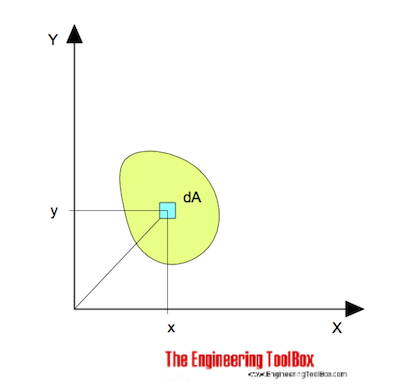
for bending around the x axis can be expressed as
Ix = ∫ y2 dA (1)
where
Ix = Area Moment of Inertia related to the x axis (m4, mm4, inches4)
y = the perpendicular distance from axis x to the element dA (m, mm, inches)
dA = an elemental area (m2, mm2, inches2)
The Moment of Inertia for bending around the y axis can be expressed as
Iy = ∫ x2 dA (2)
where
Ix = Area Moment of Inertia related to the y axis (m4, mm4, inches4)
x = the perpendicular distance from axis y to the element dA (m, mm, inches)
Area Moment of Inertia for typical Cross Sections I
Solid Square Cross Section
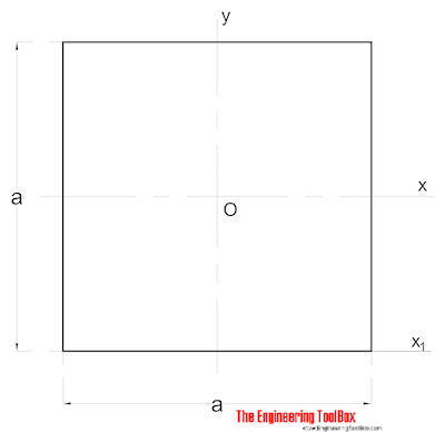
The Area Moment of Inertia for a solid square section can be calculated as
Ix = a4 / 12 (2)
where
a = side (mm, m, in..)
Iy = a4 / 12 (2b)
Solid Rectangular Cross Section
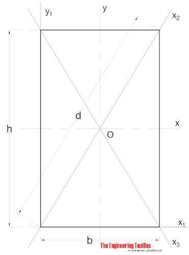
The Area Moment of Ineria for a rectangular section can be calculated as
Ix = b h3 / 12 (3)
where
b = width
h = height
Iy = b3 h / 12 (3b)
Solid Circular Cross Section
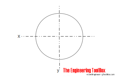
The Area Moment of Inertia for a solid cylindrical section can be calculated as
Ix = π r4 / 4
= π d4 / 64 (4)
where
r = radius
d = diameter
Iy = π r4 / 4
= π d4 / 64 (4b)
Hollow Cylindrical Cross Section
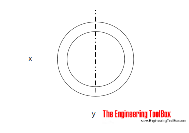
The Area Moment of Inertia for a hollow cylindrical section can be calculated as
Ix = π (do4 - di4) / 64 (5)
where
do = cylinder outside diameter
di = cylinder inside diameter
Iy = π (do4 - di4) / 64 (5b)
Square Section - Diagonal Moments
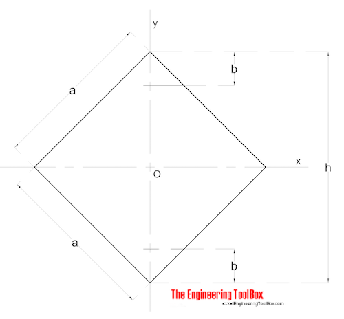
The diagonal Area Moments of Inertia for a square section can be calculated as
Ix = Iy = a4 / 12 (6)
Rectangular Section - Area Moments on any line through Center of Gravity
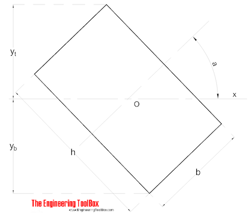
Rectangular section and Area of Moment on line through Center of Gravity can be calculated as
Ix = (b h / 12) (h2 cos a + b2 sin2 a) (7)
Symmetrical Shape
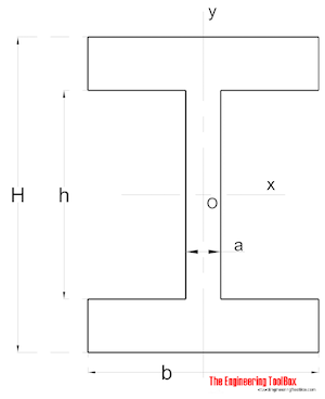
Area Moment of Inertia for a symmetrical shaped section can be calculated as
Ix = (a h3 / 12) + (b / 12) (H3 - h3) (8)
Iy = (a3 h / 12) + (b3 / 12) (H - h) (8b)
Nonsymmetrical Shape
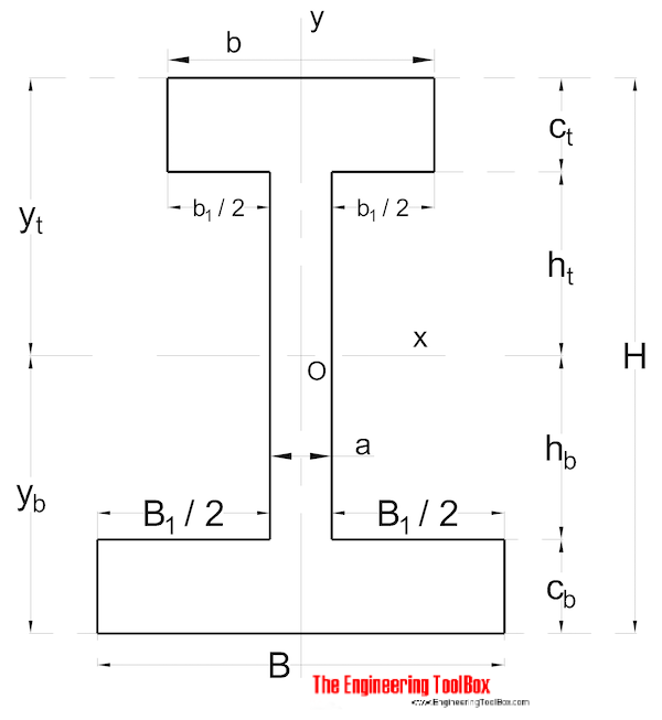
Area Moment of Inertia for a non symmetrical shaped section can be calculated as
Ix = (1 / 3) (B yb3 - B1 hb3 + b yt3 - b1 ht3)
~~~~~~~~~~~~~~~~~~~~~~~~~~~~~~
Beams - Supported at Both Ends - Continuous and Point Loads
Stress in a bending beam can be expressed as
σ = y M / I (1)
where
σ = stress (Pa (N/m2), N/mm2, psi)
y = distance to point from neutral axis (m, mm, in)
M = bending moment (Nm, lb in)
I = moment of Inertia (m4, mm4, in4)
~~~~~~~~~~~~~~~~~~
The calculator below can be used to calculate maximum stress and deflection of beams with one single or uniform distributed loads.
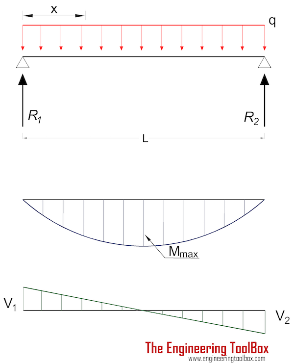
Beam Supported at Both Ends - Uniform Continuous Distributed Load
Maximum
moment in a beam with uniform load supported at both ends:
Mmax = q L2 / 8 (1a)
where
Mmax = maximum moment (Nm, lb in)
q = uniform load per length unit of beam (N/m, N/mm, lb/in)
L = length of beam (m, mm, in)
Moment in position x:
Mx = q x (L - x) / 2 (1b)
where
Mx = moment in position x (Nm, lb in)
x = distance from end (m, mm, in)
Maximum Stress
Maximum
stress in a beam with uniform load supported at both ends:
σmax = ymax q L2 / (8 I) (1c)
where
σmax= maximum stress (Pa (N/m2), N/mm2, psi)
ymax = distance to extreme point from neutral axis (m, mm, in)
- 1 N/m2 = 1x10⁻⁶ N/mm2 = 1 Pa = 1.4504x10⁻⁴ psi
- 1 psi (lb/in2) = 144 psf (lbf/ft2) = 6,894.8 Pa (N/m2) = 6.895x10⁻³ N/mm2
Maximum
deflection:
δmax = 5 q L4 / (384 E I) (1d)
where
δmax = maximum deflection (m, mm, in)
E = Modulus of Elasticity (Pa (N/m2), N/mm2, psi)
Deflection in position x:
δx = q x (L3 - 2 L x2 + x3) / (24 E I) (1e)
Note! - deflection is often the limit factor in beam design. For some applications beams must be stronger than required by maximum loads, to avoid unacceptable deflections.
Forces acting on the ends:
R1 = R2
= q L / 2 (1f)
where
R = reaction force (N, lb)
Example - Beam with Uniform Load, Metric Units
A
UB 305 x 127 x 42 beam with length
5000 mm carries a uniform load of
6 N/mm. The moment of inertia for the beam is
8196 cm4 (81960000 mm4) and the
modulus of elasticity for the steel used in the beam is
200 GPa (200000 N/mm2). The height of the beam is
300 mm (the distance of the extreme point to the neutral axis is
150 mm).
The maximum stress in the beam can be calculated
σmax = (150 mm) (6 N/mm) (5000 mm)2 / (8 (81960000 mm4))
= 34.3 N/mm2
= 34.3 106 N/m2 (Pa)
= 34.3 MPa
The maximum deflection in the beam can be calculated
δmax = 5 (6 N/mm) (5000 mm)4 / ((200000 N/mm2) (81960000 mm4) 384)
= 2.98 mm
AND TO DO THE CALCULATIONS PLEASE GO THE LINK BELOW
YOU CAN INPUT DATA A SEE JUST WHAT CONC VEL AND FORCE WILL DO